Markus,
No worries. Post away.
Jamesp,
There are some great pointers in your post. If I may point out something in the picture that you posted, it looks like the edge of that ring groove is pretty hammered. I only noticed it because I saw a post elsewhere and the person managed to chip off a pretty good chunk of piston clear up to the oil ring groove.
I would seem that lining up the circlip insertion tool is super important, and that possibly some people are confusing a swift palm against the knob of the insertion tool with the need for extreme force.
I managed to install the circlips on my pistons 1-3 the other day without any special tooling, but I think I'll remove them once my insertion tool shows up and get a really good idea for what it feels like. Needless to say, the whole bank 4-5 thing is causing me to ponder things. I'm hoping Jake's new tool hits the market soon.
Update:
Not that anyone is sitting on the edge of their seats waiting for me to update this thread, but it has taken a turn or two recently.
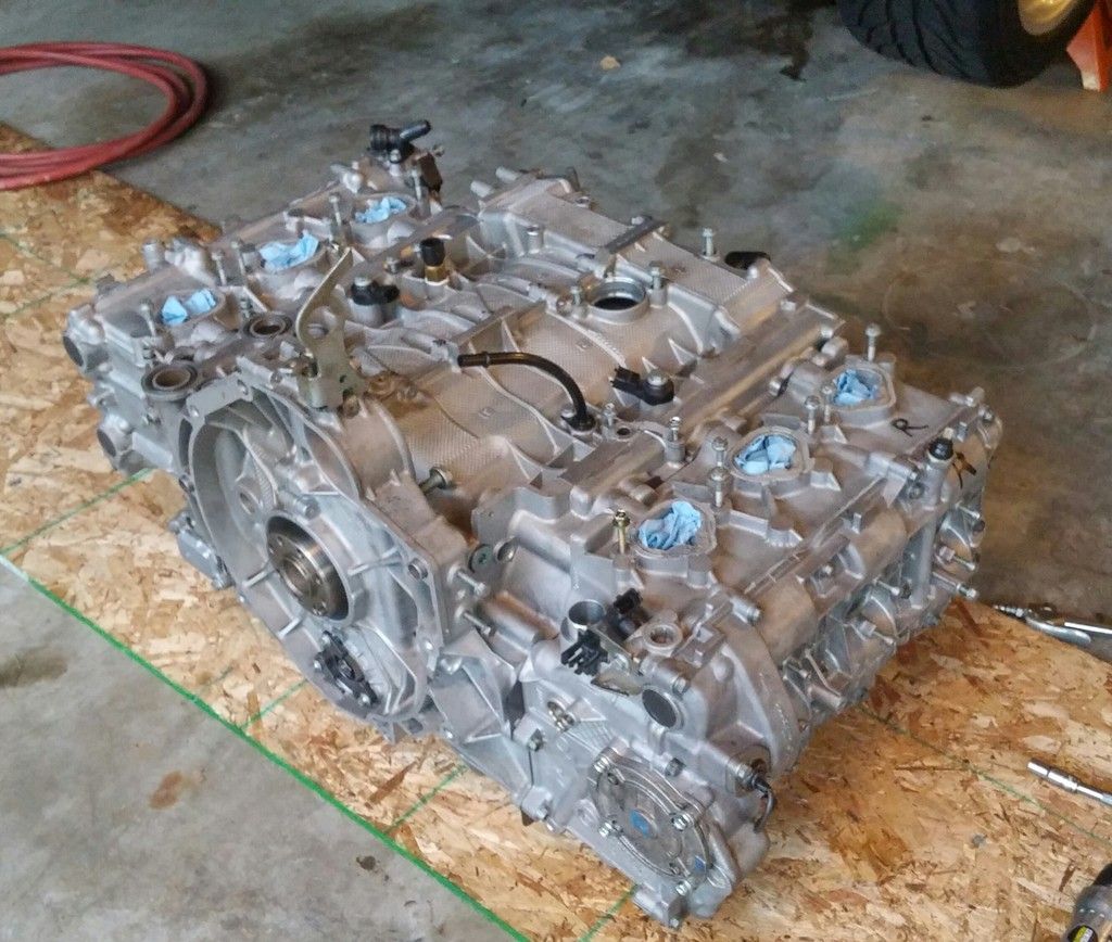
The good news is that I'm on my way back together. The bad news is that everything from the bearing carrier "out" is going to be restricted to fresh seals. For now.
My reasoning is as follows. As just mentioned by user jamesp, I have a snapped off oil ring. For those not familiar, the oil ring is in three pieces. There is a heavily perforated T shape piece that goes in the groove and there are very thin steel rings that go above and below the perforated piece. Using a conventional ring compressor it would be
very easy to get one of those super thin pieces out of shape and viola, you get a bore scratch just like I have. And a missing piece of ring that surely did some great work on its way to the filter. For the record, one of my recent purchases was an ARP tapered sleeve ring compressor which should go a long ways towards reducing the chances of buggering up another oil ring.
I did some pondering on the ring situation. In a normal engine (which the M96 is decidedly not) you would bore the cylinders to the next size up and then buy new pistons and rings to go with them. There are no off the shelf, next size up pistons for the M96. That sort of supports the idea that this is a throw away motor in Porsche's eyes and will eventually whack that line they love to publish in their ads (70% of all porsches ever made are still on the road). In the future that may only be true if you count the number of 986/996 cars with an LS or Subaru engine.
But I digress.
I was hoping to get this back together perhaps not "on the cheap", but at least not have to hang my head in shame as to what I put back inside. What I wanted to do was get fresh rings, do a bore hone to give them a new surface and hope that my scratch was diminished.
I took the case halves back to my local engine building shop, which is well known for doing V8 hot rods but he down plays any Porsche work he's done (he knows more than he lets on). His assistant pointed out my sleeve material and he held up his hands and said he would only be making my problem worse to even hone them out.
For anyone who is curious what is meant by that, removing material from the bores will also remove the high silicone content of the bore surface, leaving you with some dead soft aluminum to rub up against your steel rings. How much can you remove and still be safe? I don't know, but I'm glad that the shop I was in was honest enough to say he didn't know the answer either.
You can of course get the case halves resleeved and use stock size pistons and rings. Look up any shop that does sleeving (probably with iron sleeves), price
stock pistons, and
stock rings then do the math and you'll discover what I did: That the LN "Nickies" are the cheapest deal on earth by at least $1000. For a total throw down of about $4600 I can have my choice of 3.2, 3.4 or 3.6 liter with Nickies sleeves and JE pistons and rings.
What was not clear to me from the LN web page was whether they were selling case halves with the sleeves in them for that price or if it was exchange, or ship 'em in or what. I had to talk to someone at LN today anyway about my recent order and if anyone is curious the prices quoted on their web page are for you to send in your case halves for the work to be done. They have no stock of cases ready to rock. He told me current turn around is around 8-10 weeks.
Now I know that part at least.
So here is the part where I hang my head in shame. I don't have $4600 right now, plus the $1500-1600 for a decent set of non throw away connecting rods and another $1300+ for LN to pin my IMS and install a three row ceramic bearing (dammit, just realized I forgot to ask if they still do that).
I can set aside that kind of money but it will be probably six months or so. Again, this car is a hobby - although I'm starting to think that hookers and blow are cheaper. Even though it's a hobby I still want to drive the damn thing.
My new plan is to go with my rebuilt lower end and reuse the case halves, pistons and rings except for the oil ring that is busted off. I can't even believe I just typed that, but there it is. It just seems like trying to re-ring the thing is throwing good money (stock rings are about $250/hole) after bad (out of round bores, my scratch, etc).
My reasoning continues as follows. First, my car ran perfectly when I pulled into my garage to start this project. It didn't burn or leak any unreasonable amount of oil. The car I will pull back out of my driveway will be much better than the one I pulled in - with no metal floating around inside. Oh, and by the way I'm installing the LN filter assembly and magnetic plug.
Next, I'm going to know a heck of a lot more on my
second engine build than I will on this first one. I will be able to go to one of Jake's classes and have a heck of a lot higher chance of absorbing more information because I will have held all these parts in my hands already. And after that I'll be ready to have some case halves done and ready to go.
I've got the full support of my woman and the place to do all this.
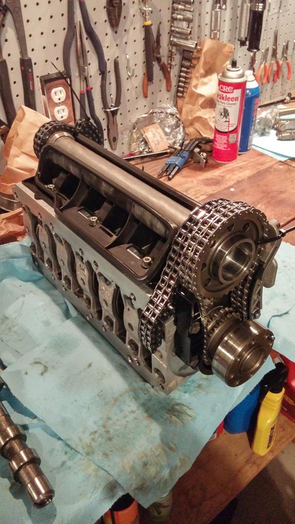
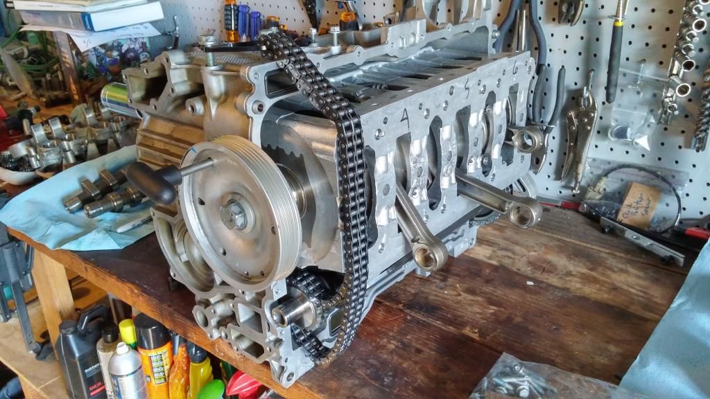
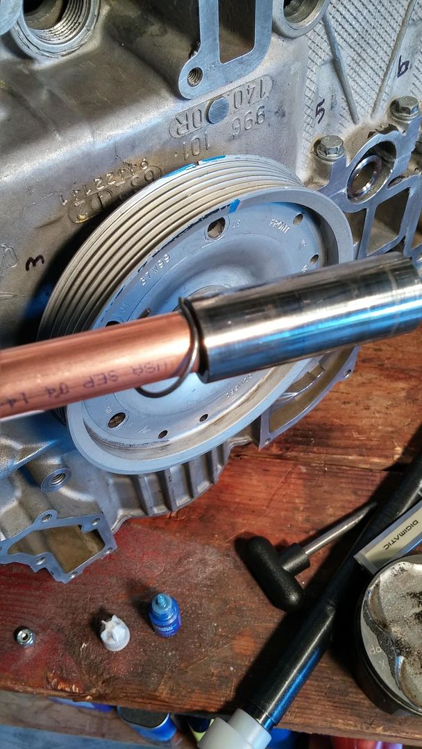
With that out of the way, here is a quick shot of my bearing carrier on the bench.
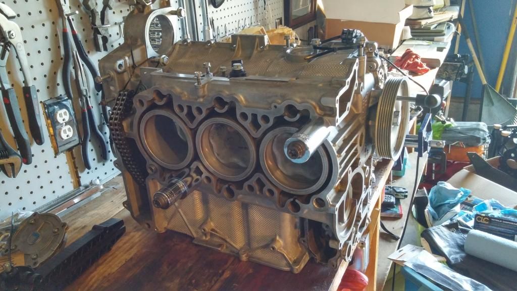
Case half for bank 1-3 is ready to go. The bad news from LN earlier today was that I won't see that tapered sleeve ring compressor until near the end of the month.
I am going to break down and source an engine stand, to answer another question posted earlier.


 Mean Motor Scooter
 The Hoe
 Avante
 Porsche
 Linear Mode


