 11-01-2014, 07:46 AM
|
#61
|
|
Registered User
Join Date: Sep 2008
Location: Agoura Hills (LA) So.Cal.
Posts: 1,574
|
Quote:
Originally Posted by kjc2050

I took it as humorous. Great thread; keep it up.
|
Same here. Love this thread.
__________________
1995 Porsche C4 Cab
2016 BMW M2, 6 Speed LBB - ED 7/2016
1997 993 Cab - Sold; 1997 993 Turbo - Sold
2001 Boxster S - Original Owner - 30K Miles -SOLD
|

|

|
|
11-01-2014, 06:30 PM
|
#62
|
|
Registered User
Join Date: Jul 2014
Location: Tacoma
Posts: 429
|
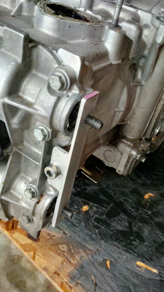
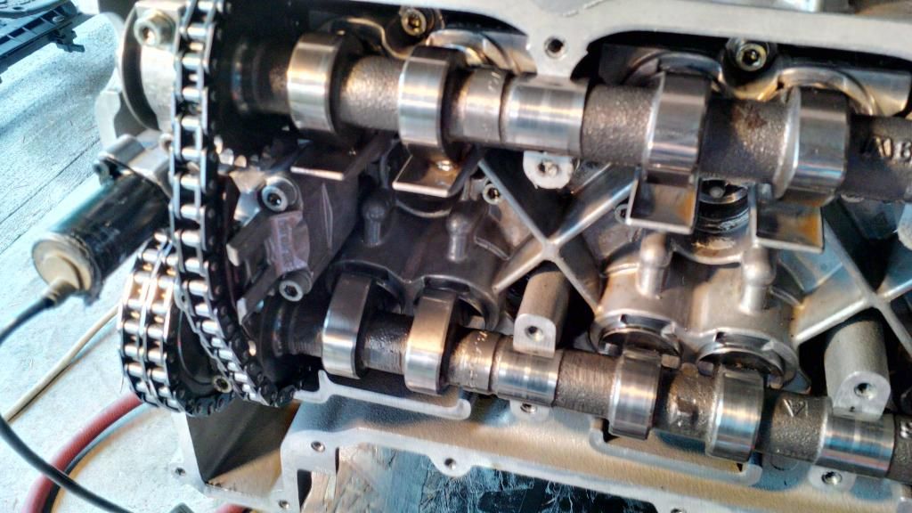
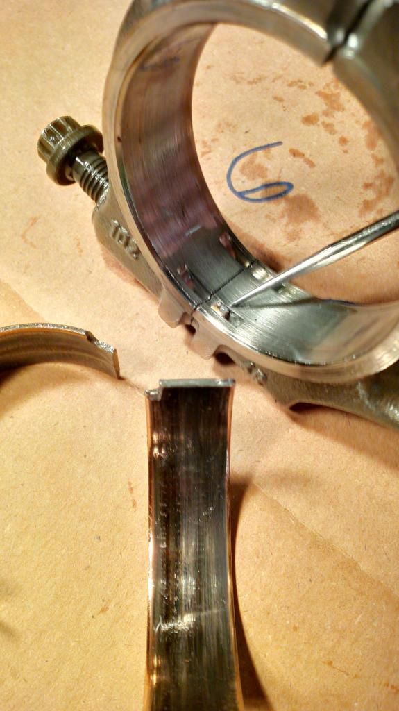
After posting up yesterday I really thought I was going out to the garage to look at some camshafts. I should have known better though, since I've read about the use of some of the special Porsche tools required to properly remove the camshaft cover and remove the cam shafts.
Put simply, if you just remove the camshaft cover the cams will want to fall out and surely they'll get all gouged up in the process. So, tool # 9634 to the rescue.
Now I noticed on 986fix.com and also "project nutrod" that the guys who were kind enough to post up their pictures made their own special tools. So it seemed fitting that I would do the same. Time to go ponder the requirements.
Tool 9634 uses the same lug used to hold the LN engineering cam locking tool, only instead of engaging the key way there are two cylindrical features which lock in the centers of the cam shafts. Time to measure the distance between cam shafts. Now I noticed that on the two web pages referenced that they show the steps they used to create their tooling but don't mention the dimensions. It can't possibly be proprietary since anyone could measure the distance on their own.
Now maybe it's not kosher to publish the dimension so I won't, but it rhymes with 112.5mm. As for the diameter of the cylindrical features, you just need to dig out the socket head cap screws that used to hold your clutch pressure plate to your flywheel. They fit perfectly in the ends of the cams.
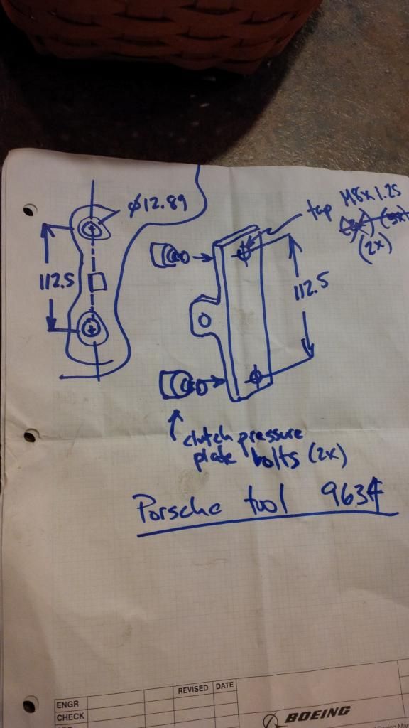
Going with that I imagined some tool made from a simple piece of angle. Two tapped holes 112.5mm apart and the clutch bolts threaded in. Then it would need a hole on the other leg of the angle, centered. The biggest hurdle would be getting a face of my new tool to line up exactly with the centerline of the two cam bolts.
I made a shopping trip with my sketch to the local home box store. I came up with a piece of L angle aluminum and after that I needed a spacer. The cheapest spacer I could come up with was a nut that was a slip fit for the M8x1.25 bolt (aka clutch pressure plate bolt) that would hold the tool to the head.
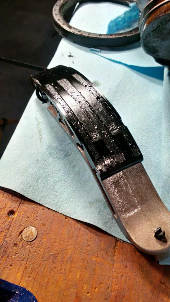
Next it was off to my son's house to commandeer the drill press I left with him. Getting the two cam bolts to line up on the same center as the inside face of my new "spacer" would be easier done than said. Behold:
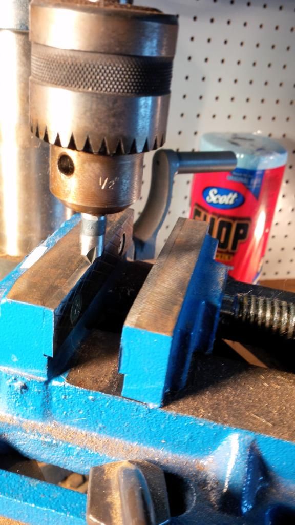
I needed a rigid way of starting the two threaded holes if I had any chance of nailing my 112.5mm goal. I chucked up a stiff drill bit which I'm going to erroneously refer to as a center drill (it's a countersink tool in real life, but the closest they had at Lowe's). Bottom line, it wasn't going to wander when starting a hole.
Chucking it up in the drill press I brought it down and rotated my table until the rear (non moving jaw) of my vise was right on the money for the tip of the "center" drill. Then I put my angle in, with the spacer (aka M10 nut) faced towards the back jaw. I could then start a hole any damn where I pleased, and then slide the work piece along the vice jaw exactly 112.5mm.
I did that by bringing my center drill down and just marking off the drill point for the future hole. Then I scribed an arc at 112.5mm. All I would have to do is loosen the vise and slide the part down until the tip of the center drill intersected with my arc.
I'm skipping a couple of steps here but this is another look
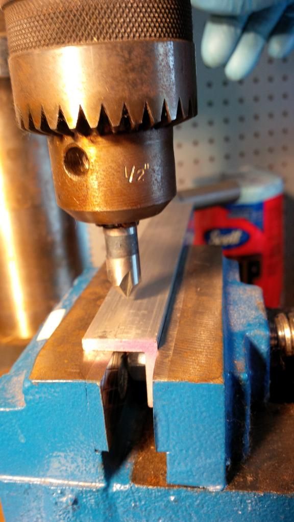
As you can see, the face of my spacer being pushed up against the rear jaw of the vise assures the holes will be exactly lined up with the lug on the cylinder head.
Last edited by flaps10; 11-01-2014 at 06:33 PM.
|
|
|
|
|
11-01-2014, 07:50 PM
|
#63
|
|
Registered User
Join Date: Jul 2014
Location: Tacoma
Posts: 429
|
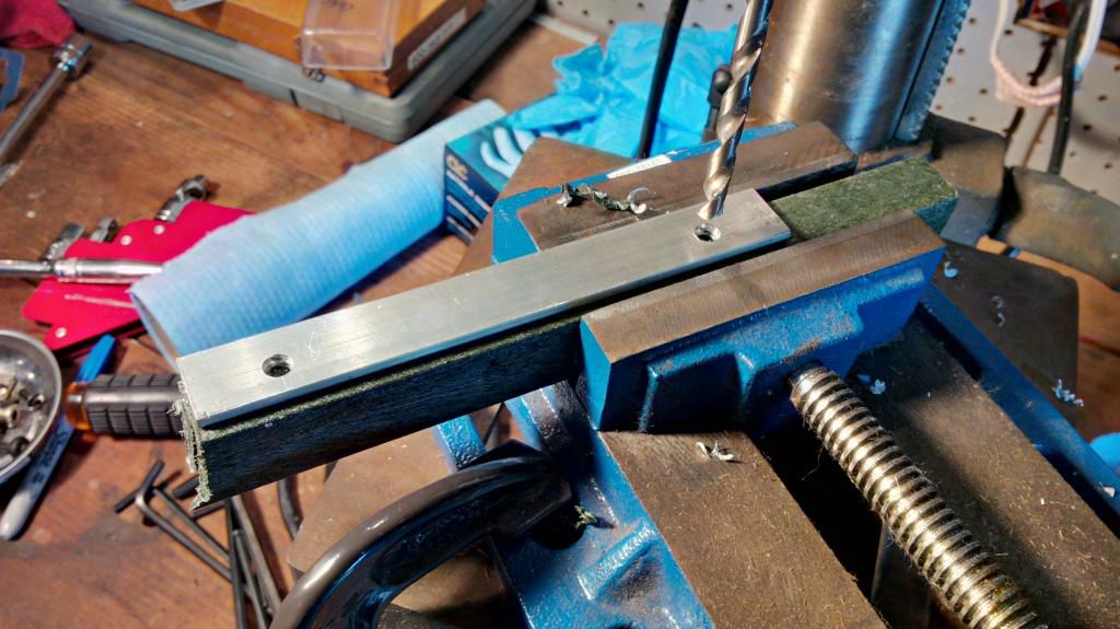
This picture is after the holes were drilled but before tapping them for the M8x1.25 bolts. In my previous setup I was aiming for accuracy but could not have drilled the holes through or the bit would hit my vise jaw.
In the pic above you'll see I flipped the part around and set it on a sacrificial plastic spacer. You'll see this plastic again later, when I use it to create the special Porsche tools used to hold the cams in place for timing purposes but for now you're looking at a scrap of plastic. All I had to do was unlock the table of my drill press and relocate the center of the holes I started, then change up to the drill I would us to pilot the tapped holes and blow them through.
Next I tapped the holes M8x1.25, and then verified that they fit the cams (they did). Then I eyeballed the stuff that would need to be removed, marked it with a sharpie pen and took a hack saw to remove the excess metal. Then I grabbed the file and made it presentable at 5'.
I learned a TON from my uncle many, many years ago about taking the time to do things right and making what you couldn't buy. Now, where I used my file to round off sharp edges he would have gone to town and probably would have applied a black crackle finish and some sort of data plate. One of these days I'm going to be as cool as my uncle.
The hole used to sock the tool down in position doesn't have to be a close tolerance hole. It just has to be a nice clearance hole. So I blew it through with a 21/64" bit and then tried to install it.
It works.
Now my tool looks a bit light duty compared to tools you might spend a ton of money on. I would have felt warmer inside had I used 1/4" thick extrusion, but then I'd have had more work to do. And truth be told the cams don't want to jump off the head when you remove the cover. They just want to be held. This tool does that. In fact when I got to the part where I pulled the cams off I had to loosen this tool to let go of the non driven ends of the cams.
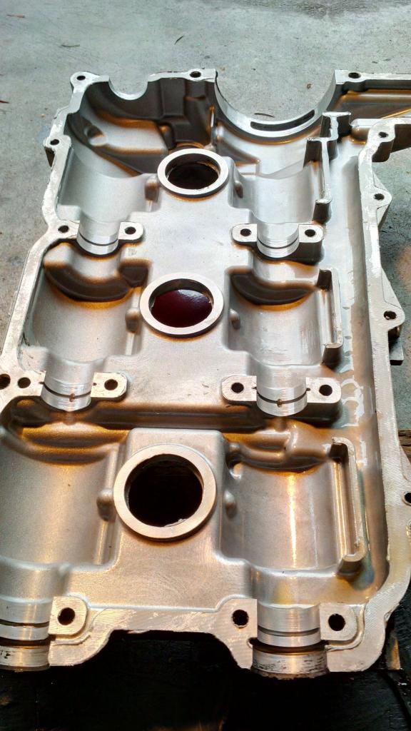
I was not horrified with what I found when the cover came off. Yet.
The worst thing I see is the cam journal (which is the inside of the cam cover) in the middle left of the pic. It looks worse in the image than it does in real life. You cannot feel any of the marks you see.
Some more exposure:
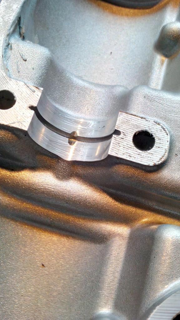
Here's that ugly cam journal inside the cam cover. Again, you can't feel any of this that you see. Looks to me like some debris has been pumped through here.
Where I stopped for the evening:
I got all the cam lifters out and I have my request in for an egg carton which I'll get after brunch tomorrow. I loosened all the hardware I could find on cam lifter carrier, but it didn't jump into my hands. I was way tired so called it quits for the day. I cleaned up my tools and the garage.
Last edited by flaps10; 11-01-2014 at 08:02 PM.
|
|
|
|
|
11-01-2014, 09:10 PM
|
#64
|
|
Motorist & Coffee Drinker
Join Date: Jul 2014
Location: Oklahoma
Posts: 3,955
|
Cool tool and great 'DIY clarity'.
Can that cam journal surface be polished or does the cover have to be replaced?
Quote:
Originally Posted by rp17
Might be a stupid question but about how much does the engine weigh?
|
Mine was 393 lbs on a bathroom scale rated to 400 lbs.
|
|
|
|
|
11-02-2014, 04:33 AM
|
#65
|
|
Engine Surgeon
Join Date: Aug 2008
Location: Cleveland GA USA
Posts: 2,425
|
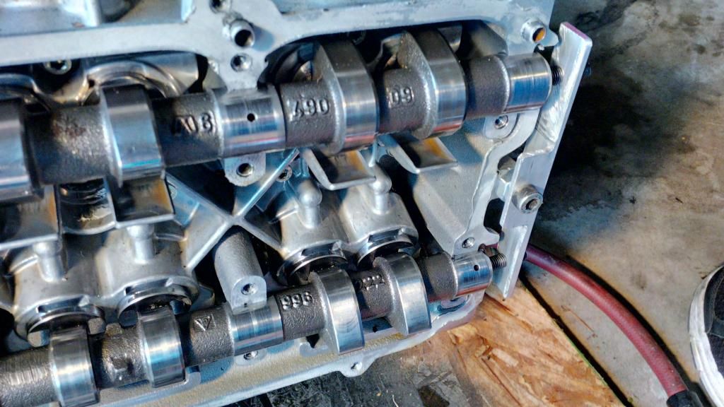
Consider reindexing the slots for the exhaust cam sprocket more toward the middle. As they are you have no room for adjustment at a later date. That later date might be really soon.
After its together spin the engine 20 times CW and then recheck cam timing. In most cases a small correction will need to be made.
__________________
Jake Raby/www.flat6innovations.com
IMS Solution/ Faultless Tool Inventor
US Patent 8,992,089 &
US Patent 9,416,697
Developer of The IMS Retrofit Procedure- M96/ M97 Specialist
|
|
|
|
|
11-02-2014, 06:47 AM
|
#66
|
|
Registered User
Join Date: Sep 2008
Location: Agoura Hills (LA) So.Cal.
Posts: 1,574
|
Quote:
Originally Posted by Jake Raby
Consider reindexing the slots for the exhaust cam sprocket more toward the middle. As they are you have no room for adjustment at a later date. That later date might be really soon.
After its together spin the engine 20 times CW and then recheck cam timing. In most cases a small correction will need to be made.
|
Class act Mr. Raby. Class act.
__________________
1995 Porsche C4 Cab
2016 BMW M2, 6 Speed LBB - ED 7/2016
1997 993 Cab - Sold; 1997 993 Turbo - Sold
2001 Boxster S - Original Owner - 30K Miles -SOLD
|
|
|
|
|
11-02-2014, 03:23 PM
|
#67
|
|
Registered User
Join Date: Jul 2014
Location: Tacoma
Posts: 429
|
Quote:
Originally Posted by Chuck W.
Class act Mr. Raby. Class act.
|
Indeed. Much appreciated.
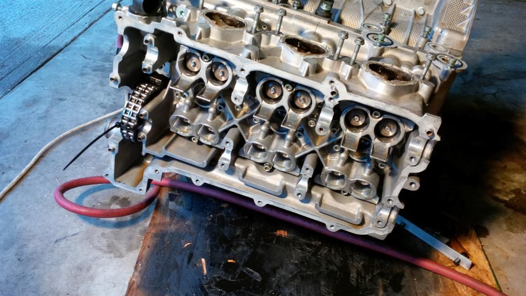
I got the lifter carrier off the cylinder head this morning. It would seem that the builder of this engine was certain that gray goo was supposed to be applied to every possible surface in order to keep the oil inside.
Starting to collect a pile.
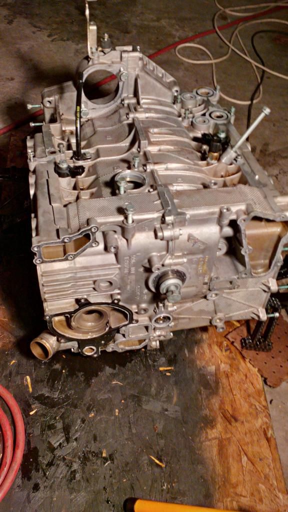
Getting the cylinder head off was a matter of removing four screws and then the large long bolts. I had neglected to remove the chain ramp pivot bolt but just by wiggling the head it was obvious where the hang up was. Out it came and the head came off.
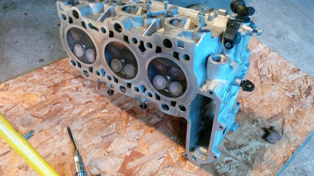
I was a bit startled to see a stray piece of metal, visible in the coolant passage at the lower left of the picture above.
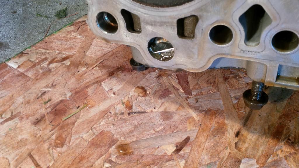
A close up.
It was that piece of foil that seals every oil and coolant jug we purchase, and somehow this one ended up in my engine. Could have been a really bad thing down the road.
This is a look the other direction:
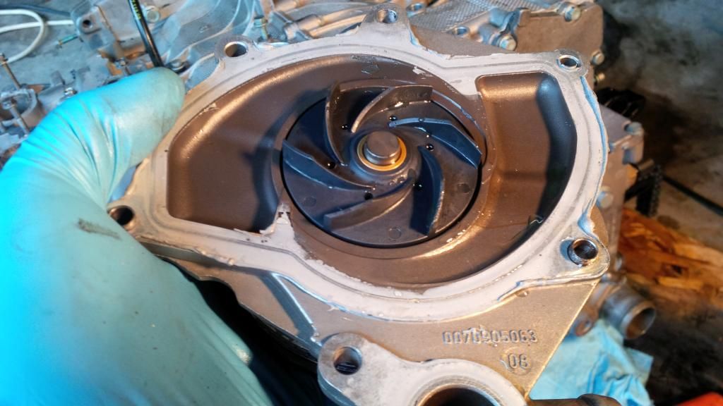
Out came my oil pump:
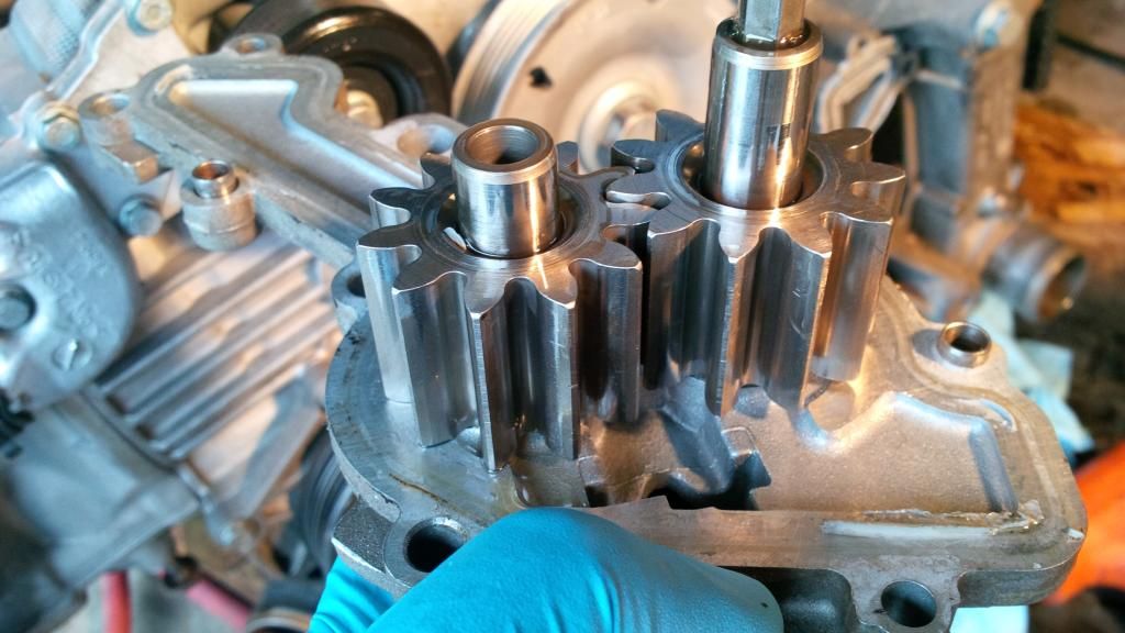
And water pump:
|
|
|
|
|
11-02-2014, 04:26 PM
|
#68
|
|
Beginner
Join Date: Mar 2013
Location: Houston
Posts: 1,659
|
The metal in the coolant passage is cause for concern, particularly since the engine appears to have had some work in the past. What does the block side of the water pump look like? Failed metal impeller water pumps are legend on this forum.
__________________
2003 S manual
|
|
|
|
|
11-02-2014, 04:51 PM
|
#69
|
|
Registered User
Join Date: Oct 2012
Location: Wake Forest, NC
Posts: 867
|
Quote:
Originally Posted by Jamesp
What does the block side of the water pump look like? Failed metal impeller water pumps are legend on this forum.
|
Isn't that a picture of the block side of the WP right above your post?
__________________
2000 Boxster S, 6 speed, Sport Package, Litronics, LED tail lights, LNE IMS-B, OBC, Skybreaker wind deflector, Arctic Silver/Graphite Grey
|
|
|
|
|
11-02-2014, 05:30 PM
|
#70
|
|
Beginner
Join Date: Mar 2013
Location: Houston
Posts: 1,659
|
Quote:
Originally Posted by kjc2050
Isn't that a picture of the block side of the WP right above your post?
|
Looks like I must have missed it multiple times as looking back I don't see it. Metal water pump impellers can machine the block which would be visible in the block after the water pump is removed. I did not find that shot in the pictures provided. If the block was machined by a metal impeller, metal in the coolant passages could be expected. This could obstruct the coolant flow resulting in specific areas of the engine overheating. In any event to me, finding FOD in the coolant passages indicates a complete tear down to clean out the coolant galleys. That's a big deal, but allows building the engine up from the crank out. My engine had 120k on it, and the bearings were shot with dealer service intervals / Mobile 1 oil changes as recommended by Porsche. The timing chains off the IMS can also be changed if the block is split which is a benefit.
__________________
2003 S manual
|
|
|
|
|
11-03-2014, 03:06 AM
|
#71
|
|
Registered User
Join Date: Oct 2012
Location: Wake Forest, NC
Posts: 867
|
Quote:
Originally Posted by Jamesp
Looks like I must have missed it multiple times as looking back I don't see it. Metal water pump impellers can machine the block which would be visible in the block after the water pump is removed. I did not find that shot in the pictures provided.
|
Sorry, this is a matter of semantics. I interpreted "what does the block side of the water pump look like" as "what does the side of the water pump that mates to the block look like," but what you actually meant was "what does the block look like where the water pump mounts to it?" :-)
__________________
2000 Boxster S, 6 speed, Sport Package, Litronics, LED tail lights, LNE IMS-B, OBC, Skybreaker wind deflector, Arctic Silver/Graphite Grey
Last edited by kjc2050; 11-03-2014 at 03:09 AM.
|
|
|
|
|
11-03-2014, 06:34 AM
|
#72
|
|
Registered User
Join Date: Mar 2014
Location: Eastern NC
Posts: 701
|
Quote:
Originally Posted by Jamesp
The metal in the coolant passage is cause for concern, particularly since the engine appears to have had some work in the past. What does the block side of the water pump look like? Failed metal impeller water pumps are legend on this forum.
|
The picture does show a foil tab that seals a bottle of some sort. Maybe from the previous owner applying IMS Bearing Repair in a Can.
|
|
|
|
|
11-03-2014, 10:09 AM
|
#73
|
|
Registered User
Join Date: Jul 2014
Location: Tacoma
Posts: 429
|
Quote:
Originally Posted by BFeller
The picture does show a foil tab that seals a bottle of some sort. Maybe from the previous owner applying IMS Bearing Repair in a Can.
|
Well apparently they didn't read the instructions, or didn't use enough. cough.
I didn't have time for a pic this morning as I suited up for the ride in, but I did look at the crankcase side of water pump housing. It is slightly discolored from the coolant but it is 100% "as cast" and doesn't have a mark on it.
|
|
|
|
|
11-06-2014, 05:45 PM
|
#74
|
|
Beginner
Join Date: Mar 2013
Location: Houston
Posts: 1,659
|
Quote:
Originally Posted by flaps10
Well apparently they didn't read the instructions, or didn't use enough. cough.
I didn't have time for a pic this morning as I suited up for the ride in, but I did look at the crankcase side of water pump housing. It is slightly discolored from the coolant but it is 100% "as cast" and doesn't have a mark on it.
|
That's good news. Parts are expensive, but you are in a position to turn back the clock on the parts in your engine that tend to wear. My rings had 120K on them, and while clearly worn (about 1/3 gone), they sealed fine, so I kept the $1200 (wow! price rings for anything else) but replaced the really worn parts like the bearings which were down to the steel backing. Check out Gaudin Porsche for good deals, but watch out for shipping. Also, if you are going to replace your IMS bearing do a little research on bearings in general which helps in the decision on what to put back in. I liked the Pelican bolt and seal, but not the bearing due to the seal. Keep up the great work and thanks for the post!
__________________
2003 S manual
|
|
|
|
|
11-08-2014, 07:09 PM
|
#75
|
|
Registered User
Join Date: Jul 2014
Location: Tacoma
Posts: 429
|
I had a post all typed up earlier with pictures, etc of where I had managed to get to on Friday night, then had a failure to click "Submit Reply".
Well it basically contained this picture:
Since I was practiced up, removing the other cam cover, cams, lifter carrier and finally cylinder head was pretty straight forward. I had also made a comment in the post about how I've come to the conclusion that during dismantling a Porsche engine if it requires anything more than a nudge with the rubber hammer or gently prying at the pretty healthy spots the designers left you, you missed a fastener.
[sidetrip]
Back in the day I had a 75 Honda Civic 1200 and it blew a head gasket. The manual described how to get all the way down to removing the head bolts and then pointed out two (pathetic in comparison to what the M96 designers left us) locations you could pry ever so gently, but admonished that "what ever you do, don't pry at the gasket surface". (Duh). Let me tell you something, that gasket was STUCK on. I ended up devising a way to allow me to use my floor jack from under the car to push on the only spots allowed and it damn near lifted the car off the ground before the gasket came loose. Compared to that, the Porsche is a dream.
[/sidetrip]
Today's project was to get the case split. So I did.
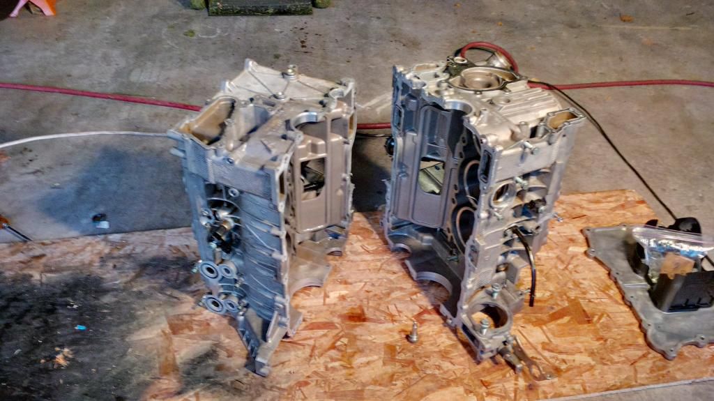
I swear to you, that's not a crescent wrench in the back ground. It's not. Really.
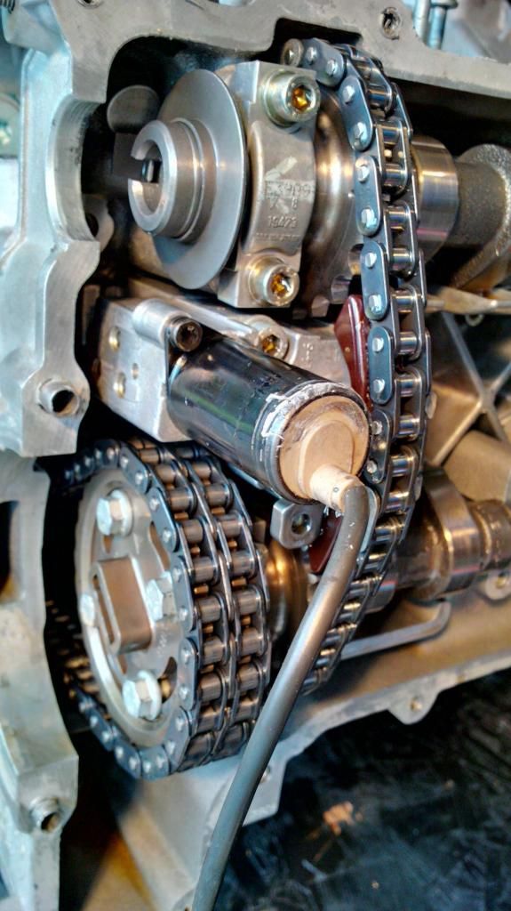
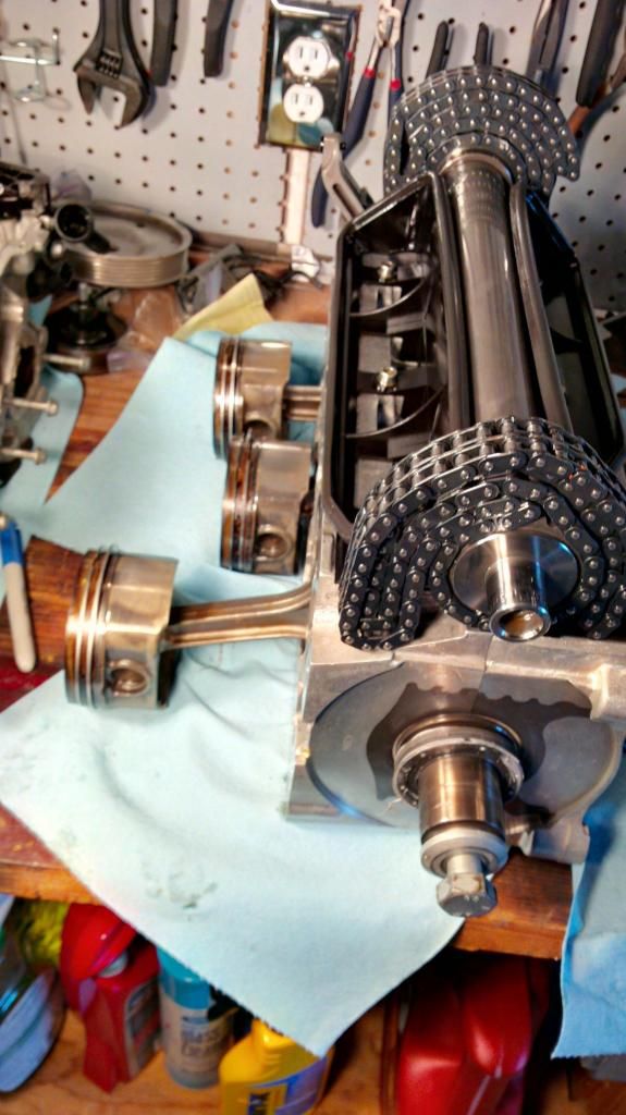
Chain ramp for the IMS/crank shaft chain. On to the shopping list. The ramps for the cam chains looked much newer.
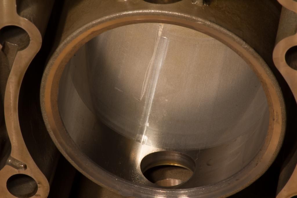
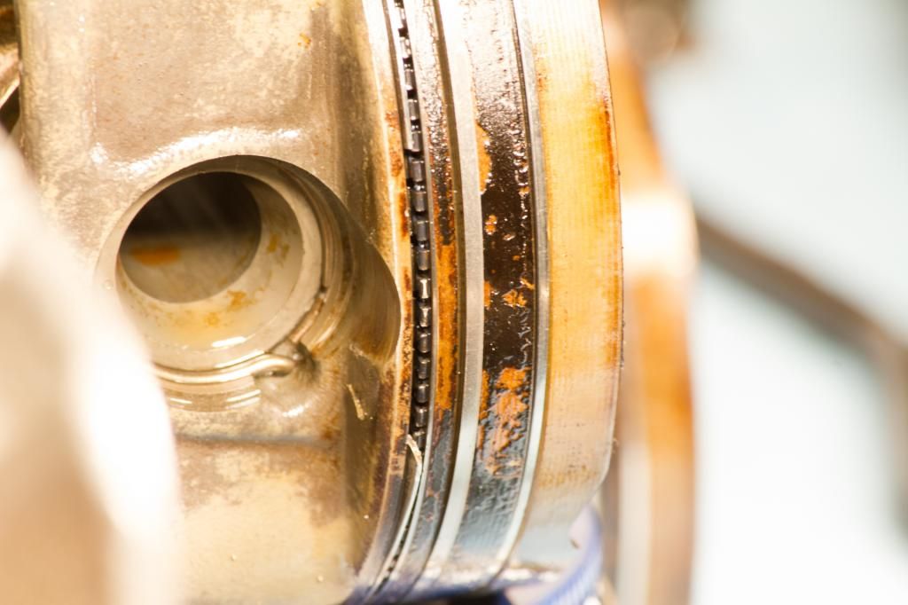
Looking over the pistons I could see some very light scoring on them, mostly between the crown of the piston and the first ring. #1 cylinder is the worst one. But the rings look damn smooth and the bores of the cylinders looked absolutely brand new in some cases, and one or two with a few very fine linear scratches. I made a point to head back after I had everything situated on my work bench to go back and wipe out those bores and really take a look
Houston, we have a problem.
I thought it was the strange way light shines on stuff that is dripping with oil but when I wiped the bore of my #5 cylinder I noticed a significant scratch. Shown under two different lighting scenarios so you can see the best. With bare fingers it is just possible to feel the scratches. I did my best to light them well for the pictures.
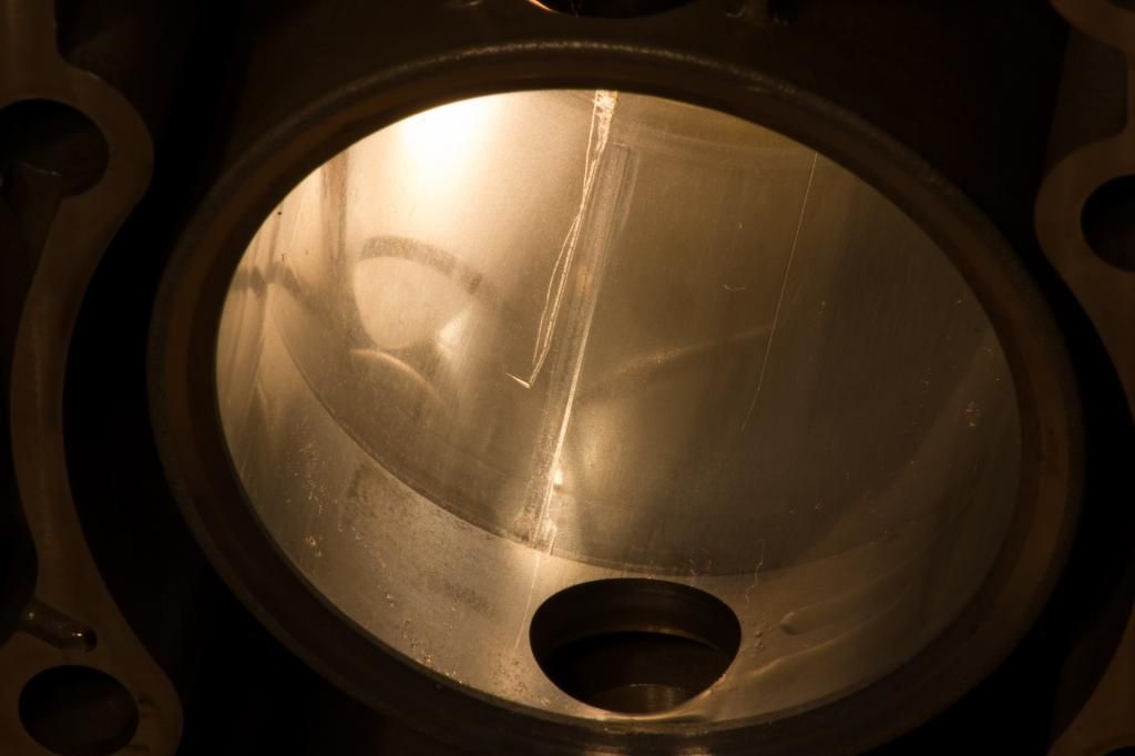
I had to orient myself with the way the crankcase was situated and then move to the bench to see if I could see any corresponding damage. I was worried that I would find where a wrist pin snap ring had popped out, but it seems to be secure. Looking on, it didn't take long to notice.
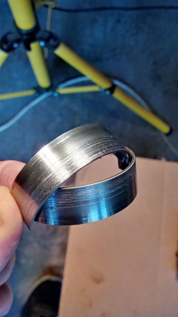
Here's what you see at first:
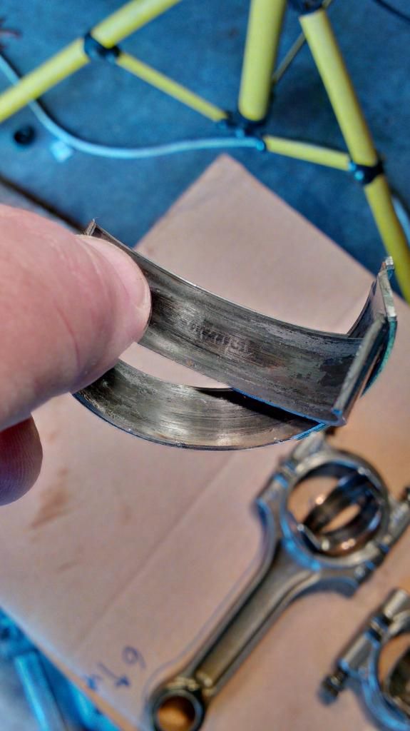
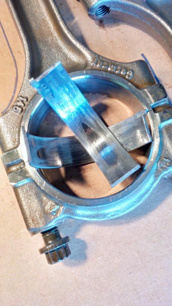
Then you zoom in:
There's supposed to be a break in the ring, but it's not supposed to be over an inch long. My guess is this is an assembly mistake, most likely the last time someone was in here. The ring material is really thin and it would not be that difficult to have snagged and got a piece crushed into the cylinder wall.
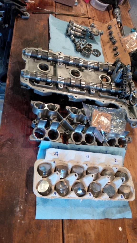
After taking the pictures here I cleaned up my tools and called it a night. Tomorrow I'll need to obtain the correct sockets for the bearing carrier and connecting rods.
Stay tuned as I dig deeper.
|
|
|
|
|
11-09-2014, 02:03 PM
|
#76
|
|
Registered User
Join Date: Jul 2014
Location: Tacoma
Posts: 429
|
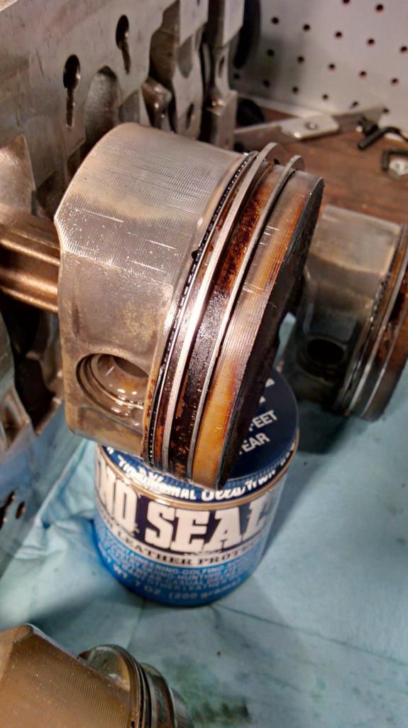
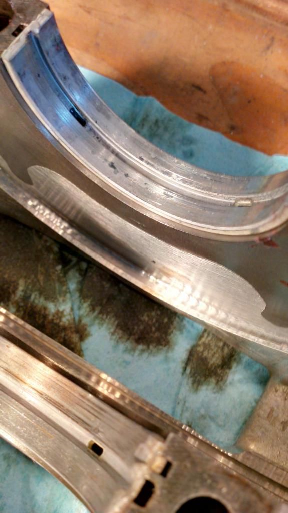
And this, ladies and gentleman, is why you do a complete tear down when you find metal in the filter.
This is cylinder #6. The bearing even appears to have mileage on the outside (i.e. it's a spun bearing).
tick, tick, tick...boom. I read that somewhere.
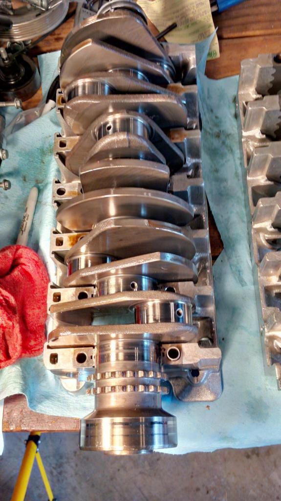
The good news for today is that it appears that my crank is in pretty good shape. I believe a basic polishing of the journals and I'll be okay.
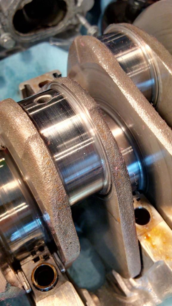
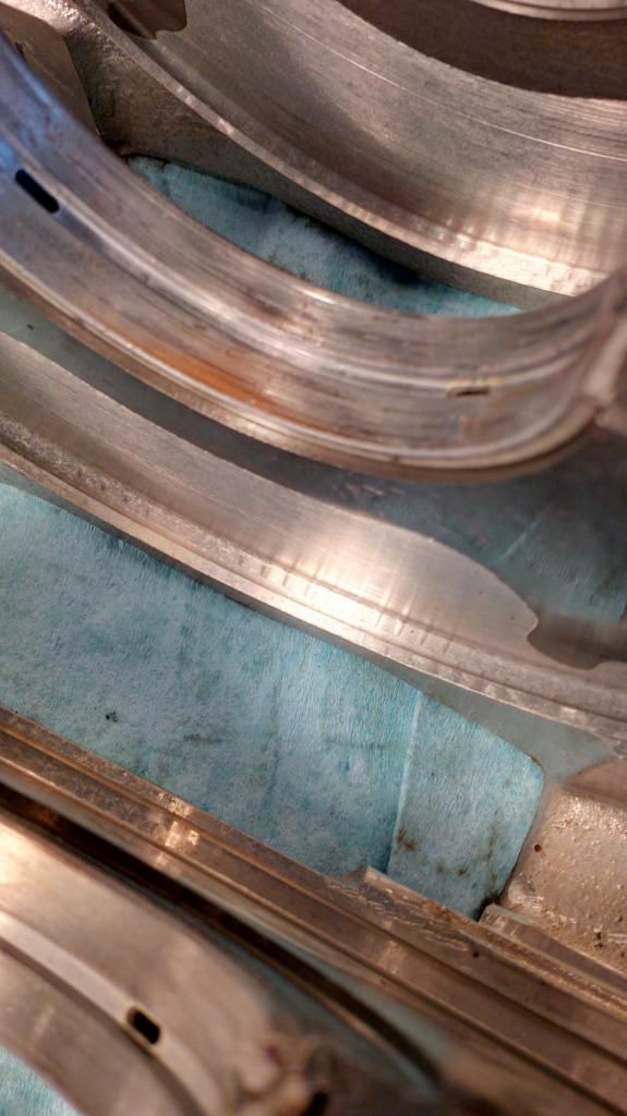
The good.
The bad. My main bearings are ugly.
So, it's apart. I'd appreciate the opinions of anyone who has actually turned wrenches themselves on a M96 engine, or at least an engine, on what I've uncovered.
I've got a couple of local shops picked out that do ultrasonic cleaning. They happen to be shops that build hot rods, so I'm assuming they can also handle polishing a crankshaft.
My wrist pins look great. ")
"Other than that Mrs Lincoln, how was the play?"
|
|
|
|
|
11-09-2014, 02:38 PM
|
#77
|
|
Motorist & Coffee Drinker
Join Date: Jul 2014
Location: Oklahoma
Posts: 3,955
|
You call those bearings bad? I bet you could have gotten another 1,000-1,500 miles out of 'em.
Mail them to me, I'll replace mine with it:

:dance:
Great pics and description. I can't wait for the assembly (you too I suppose).
I was going to put my 2.7 in today, but found out I can't get spark plugs locally, so I'm waiting a day or two for shipping rather than doing it with the engine in.
|
|
|
|
|
11-09-2014, 03:51 PM
|
#78
|
|
Registered User
Join Date: Sep 2013
Location: Montreal, QC. (currently expat to Shanghai)
Posts: 3,249
|
One of favorite thread on 986forum atm. Got to say thanks to the OP for taking the time and throwing those awesome pics at us. Top man x100
quality work, love it. Keep it going man
__________________
______________________________
'97 Boxster base model 2.5L, Guards Red/Tan leather, with a new but old Alpine am/fm radio.
|
|
|
|
|
11-10-2014, 01:40 AM
|
#79
|
|
Registered User
Join Date: Oct 2012
Location: Germany
Posts: 43
|
I had that twice in my life, but on a motorcycle engine quite a while ago. A few thouhgts.
Root cause is usually a lack of oilf pressure / flow in the bearing. If the engine is very old and worn the gap may be too high to maintain enough pressure. If the engine is not worn, there may be a problem with the oil pump or an oil line is clocked. Both happened to me. I think it should be possible to grind and polish the crank to the next smaller bearing diameter as it looks. But you have to measure first.
If the bearing has really turned inside the piston rod, you have to change the rod. But I'm surprised that the clips at the corner of the bearings are not broken. When it happened to me the engine got totally overheated in a minute and the bearing was complety destroyed.
|
|
|
|
|
11-10-2014, 10:00 AM
|
#80
|
|
Registered User
Join Date: Jul 2014
Location: Tacoma
Posts: 429
|
Quote:
Originally Posted by hemonu
snip
But I'm surprised that the clips at the corner of the bearings are not broken. When it happened to me the engine got totally overheated in a minute and the bearing was completely destroyed.
|
You know, I had put my tools away and gone about my life for a couple of hours when I had the exact same thought. So I went back out and took a careful look.
As you can see, both tabs are knocked off. I'm pointing at one of them still where it is supposed to live. The other one presented itself when I first removed the rod and bearing. It was just sitting on the crank and at the time I didn't know where it came from.
It would appear rods come in sets of six, and they're about $1500. I'd like to think I could get a single rod and have them all balanced as a set.
That I can tell, there are no scratches on the crank that would justify turning it to the next size down (which btw, aren't commonly available for the M96 from my first glance), but would respond well to a polish job.
I'm making a call to a local hot rod shop that has the capacity to do ultrasonic cleaning and do the polish work.
|
|
|
|
 Posting Rules
|
You may not post new threads
You may not post replies
You may not post attachments
You may not edit your posts
HTML code is On
|
|
|
All times are GMT -8. The time now is 05:36 AM.
| |


 Parts Car, car parts
 Honda Del Sol(s)
 "Hers"
 My Original '99
 The 78 F350
 This
This That
That The S 2.5
 Other
Other Boxster S
 Genesis 3.8
 Boxster 986 S
 BMW 330d
 Linear Mode


