 10-02-2010, 06:40 PM
|
#61
|
|
Registered User
Join Date: Sep 2006
Location: California
Posts: 713
|
^^ Brilliant! Love the innovation...
__________________
http://farm4.static.flickr.com/3420/...90927559_o.jpg
Some stuff for sale: M030 S 24mm front sway bar, M030 base 19.6mm rear sway bar, 996 GT3 OEM Porsche Motorsport front strut mounts monoball "camber plates"
WTB: looking for some 5-7mm spacers with extended bolts
|

|

|
|
10-02-2010, 07:56 PM
|
#62
|
|
Registered User
Join Date: Jan 2007
Location: Depends on the day of the week....
Posts: 1,400
|
Very ingenious indeed. Unfortunately, you are going to need more than just a tool to turn the cam to get it back into time. You really need the timing tools, and the auxiliary tensioners.
__________________
Boxster S
|
|
|
|
|
10-03-2010, 05:15 AM
|
#63
|
|
Registered User
Join Date: Sep 2004
Location: Atlanta
Posts: 1,820
|
Quote:
|
Originally Posted by Cloudsurfer
Very ingenious indeed. Unfortunately, you are going to need more than just a tool to turn the cam to get it back into time. You really need the timing tools, and the auxiliary tensioners.
|
what makes you think that? i understand the process fairly well, but i've never timed one of these.
|
|
|
|
|
10-03-2010, 09:17 AM
|
#64
|
|
Registered User
Join Date: Dec 2009
Location: Orange County, CA
Posts: 2,013
|
Quote:
|
Originally Posted by Cloudsurfer
Very ingenious indeed. Unfortunately, you are going to need more than just a tool to turn the cam to get it back into time. You really need the timing tools, and the auxiliary tensioners.
|
Ok it seems that the cam on the picture has jumped one teeth, and the cam obviously is still connected to the timing chain.
Question, if you 'loose' the chain tension as much as possible, would this allow you to rotate the cam (jumping teeth on purpose, one at the time) until you get back to the timing mark?
The cam phasing I have done in the past has always been on 'belted' engines, never with a chain which must be much harder, is this doable at all?
Or do you have to remove the valve cover to remove the chain from the cam sprocket, re-align the cam and then re-install the chain?
My questions here are pure curiosity and personal learning purposes, no criticism intended to anyone else comments.
.
|

|
|
|
10-03-2010, 11:45 AM
|
#65
|
|
Registered User
Join Date: Jan 2007
Location: Depends on the day of the week....
Posts: 1,400
|
Quote:
|
Originally Posted by insite
what makes you think that? i understand the process fairly well, but i've never timed one of these.
|
Well, the first thing I would do is visually check if the chain did slip a tooth or not. If you put the engine at TDC, and the slot on the cam is parallel to the line of the head/ valve cover joint, you can be fairly certain it's in time (in your picture, it is not parallel, so if the crank pulley is at TDC you are likely off one tooth). If you pull off the oil extraction pump (take note of its orientation, as they use the same part for both banks, but in different orientation) in the head, you'll see a chainwheel, which is bolted to the exhaust cam by 4 10mm bolts. The chainwheel has slots to allow for adjustment. The intake cam (as I'm sure you know) is driven off the exhaust cam via a separate chain and this contains the VarioCam tensioner. So, if the timing is off on the exhaust, it is also off on the intake. The timing mark, which the timing tool fits into, is on the intake cam. The tool merely holds the cam stationary while bolted to the head.
Hypothetically, if the chain slipped one tooth, you could be able to remove the tensioner and move the chain over one tooth the other way and be done (you'd need the valve cover off for this) but I've never tried doing this. However, to actually time the engine, you must loosen those 4 10mm fasteners, and do the procedure. I would roll the engine over and check both sides if you get stuck doing this. The tool only fits into the cam one way, so if it won't fit on bank 1-3, it would fit into bank 4-6, so if you are timing bank 1-3, you'd have to roll the engine over a turn. When timing the whole engine, you time one bank, then roll the engine 360, then time the other. I then roll the engine several times and double check things. For a 5 chain motor, you do need the auxiliary tensioners, which place a precise amount of tension on the chains. Supposedly you can time a newer, 3 chain motor without these, but you do need the tensioners on a 5 chain motor.
The 10mm bolts holding the chainwheel to the exhaust cam should be in the middle of their adjustment range, so you should have plenty of range to move either way during the timing process. The easiest way of re-timing your one bank would be to move the crank until you can fit the timing tool into that side's cam, lock the tool down, loosen the adjustment bolts on the cam, then roll the engine backward and then forward (to take any potential slack out of the chain) until you hit TDC (you only want to move forward when coming up to TDC), lock the crank with the fixing pin, and then tighten the 4 10mm fasteners (10 pound torque if I remember). Then, roll the engine 2 full revolutions, and re-check.
Like I said, if you get stuck doing this, I would check both banks while you have the engine out of the car and it's pretty easy to do.
Personally, I find the way you time these to be very imprecise, as there is potential variation in way too many places (where the TDC mark is on the pulley, variation in machining those slots into the non driven side of the cam during manufacturing, variation in tolerances in the tool, etc) but short of figuring out "true" TDC with a dial gauge on piston 1 or 4, and knowing the overlap numbers, it is what it is.
__________________
Boxster S
|
|
|
|
|
10-05-2010, 12:18 PM
|
#66
|
|
Registered User
Join Date: Dec 2009
Location: Orange County, CA
Posts: 2,013
|
Quote:
|
Originally Posted by insite
what makes you think that? i understand the process fairly well, but i've never timed one of these.
|
Ok, after reading several times Cloudsurfer's excellent and detailed description, the $85/hr and the cardbox on the back of the SUV makes sense to me ")
|
|
|
|
|
10-05-2010, 01:32 PM
|
#67
|
|
Registered User
Join Date: Sep 2004
Location: Atlanta
Posts: 1,820
|
i talked to jake; he thinks the auxiliary tensioners are total bs and completely unnecessary.
i will be timing the motor with no special tools & will post the procedure w/ pics when i do so. if i don't get to it wednesday, it will be awhile; probably won't get to work on it again until the 16th.
Last edited by insite; 10-05-2010 at 01:34 PM.
|
|
|
|
|
10-05-2010, 03:41 PM
|
#68
|
|
Registered User
Join Date: Jan 2007
Location: BC
Posts: 1,354
|
Quote:
|
Originally Posted by insite
probably won't get to work on it again until the 16th.
|
Jeez, I don't know if I can wait that long. Talk about living vicariously through someone else! 
__________________
2001 Boxster, 5 spd, Seal Grey
|
|
|
|
|
10-07-2010, 04:56 AM
|
#69
|
|
Registered User
Join Date: Sep 2004
Location: Atlanta
Posts: 1,820
|
ok, timed the car yesterday. very straightforward & easy; no need for any funky tools.
to do this right, you'll need a couple of spare parts:
(3) green camshaft plugs (996.104.215.54)
(8) microencapsulated bolts (900.385.275.01)
(2) o-rings (996.107.221.51)
(1) tube of green loctite
first, we need to explain some things. top dead center (TDC) occurs when a piston is at its uppermost position within the cylinder. it's the point at which the piston stops travelling up and begins travelling down. the tricky part is that TDC occurs TWICE during an engine's 4 cycles. the first time is on the compression stroke & the second time is on the exhaust stroke.
per the factory shop manual, we want to be at TDC compression when we time bank 1 (cylinders 1-3) and TDC exhaust when we time bank 2 (cylinders 4-6).
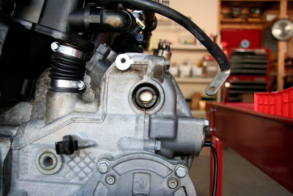
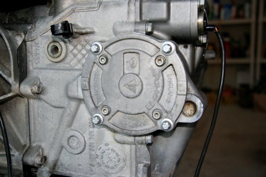
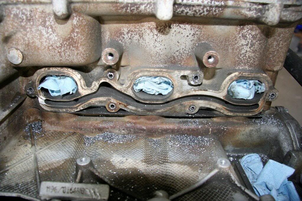
first things first. in the picture below, we're looking at the front of the engine. if the engine were in the car, we'd be looking back through the firewall toward the rear of the vehicle. bank 1 is on the left and bank 2 is on the right.
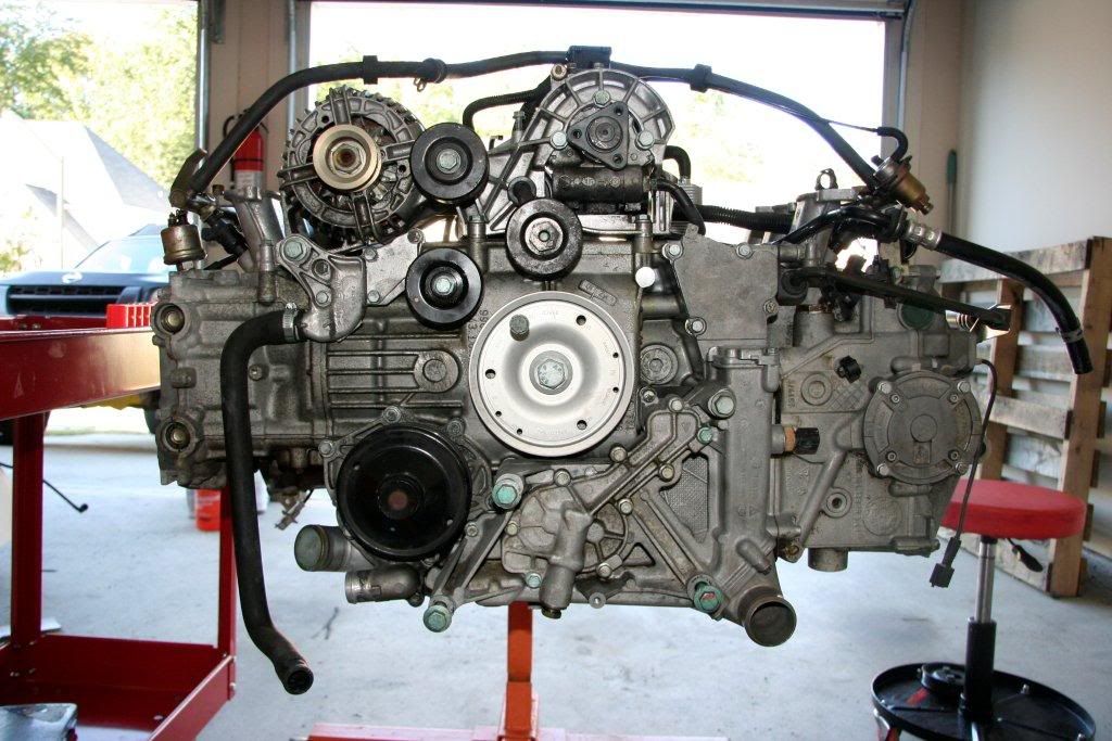
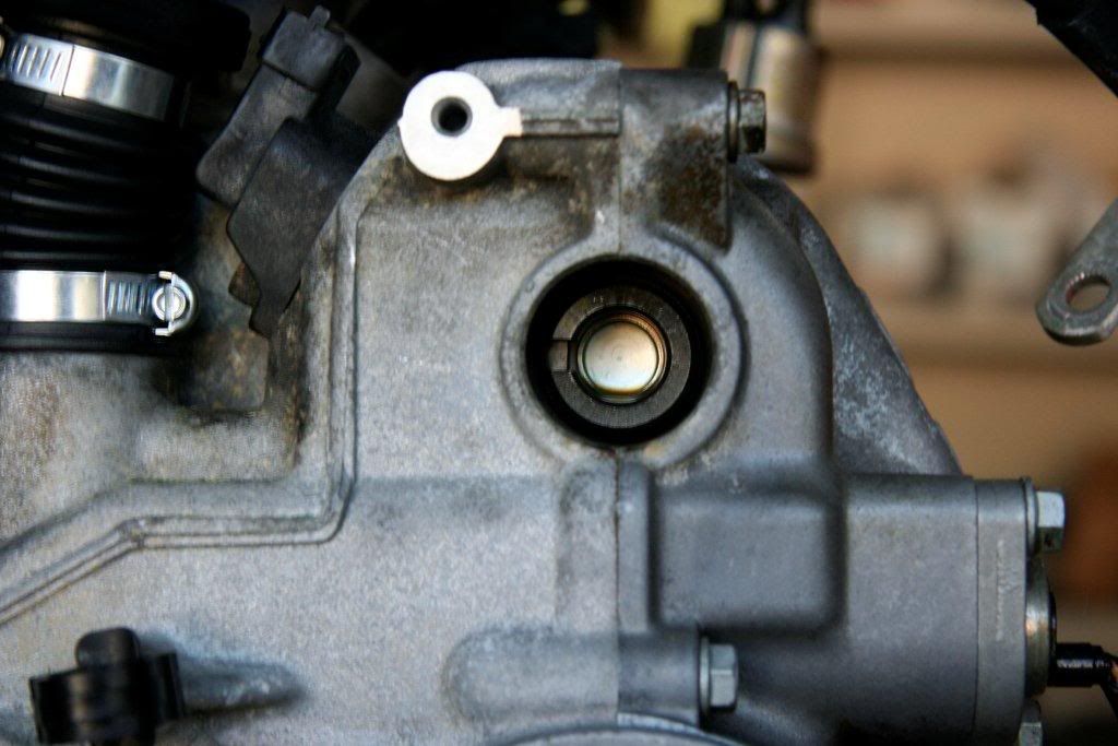
now we need to remove three of the little green camshaft plugs from the motor. there are six total cam plugs in the motor. in the photo above, you would normally see three. there would be three on the other side as well. they're already removed in this photo.
on the left side would be two plugs. remove the bottom one. on the other side of the motor on the other head, remove the bottom one. on the flywheel side of bank 1, there is only one plug. remove it.
what we've done is to remove the cover for the timing side of the exhaust cams and the index side of the intake cams. more on this in a minute.
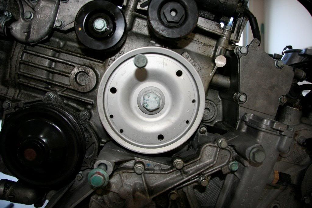
now, put a 24mm wrench on the crank pulley and rotate the engine CLOCKWISE until you get close to TDC.
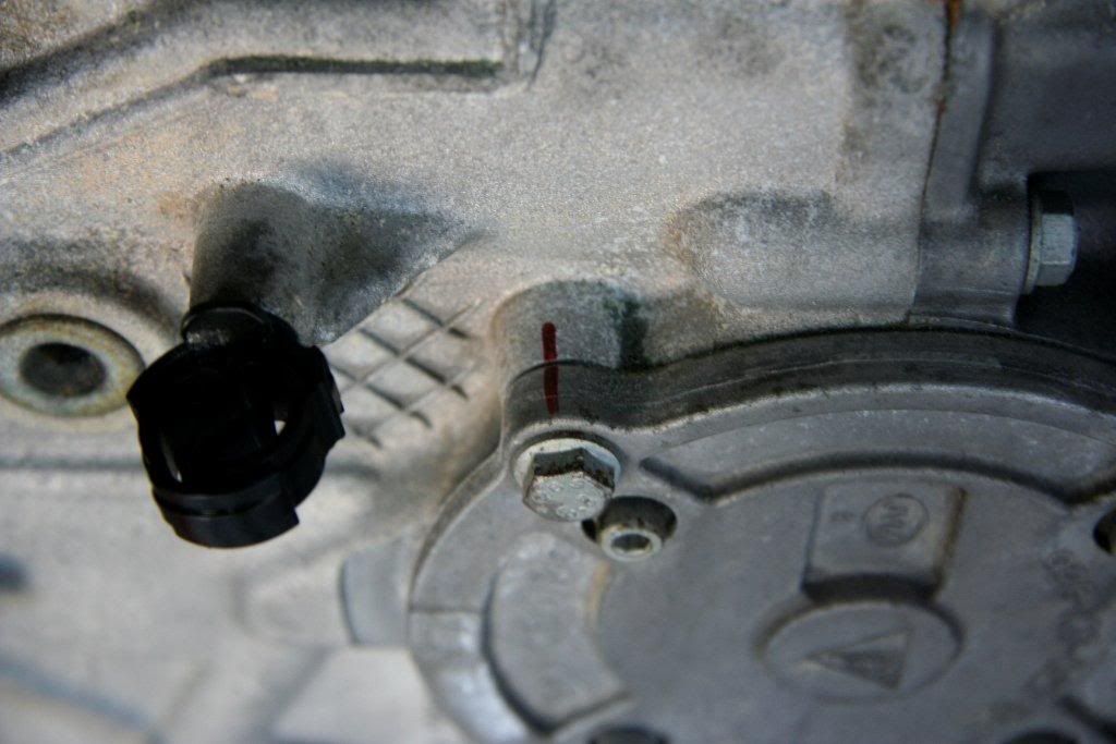
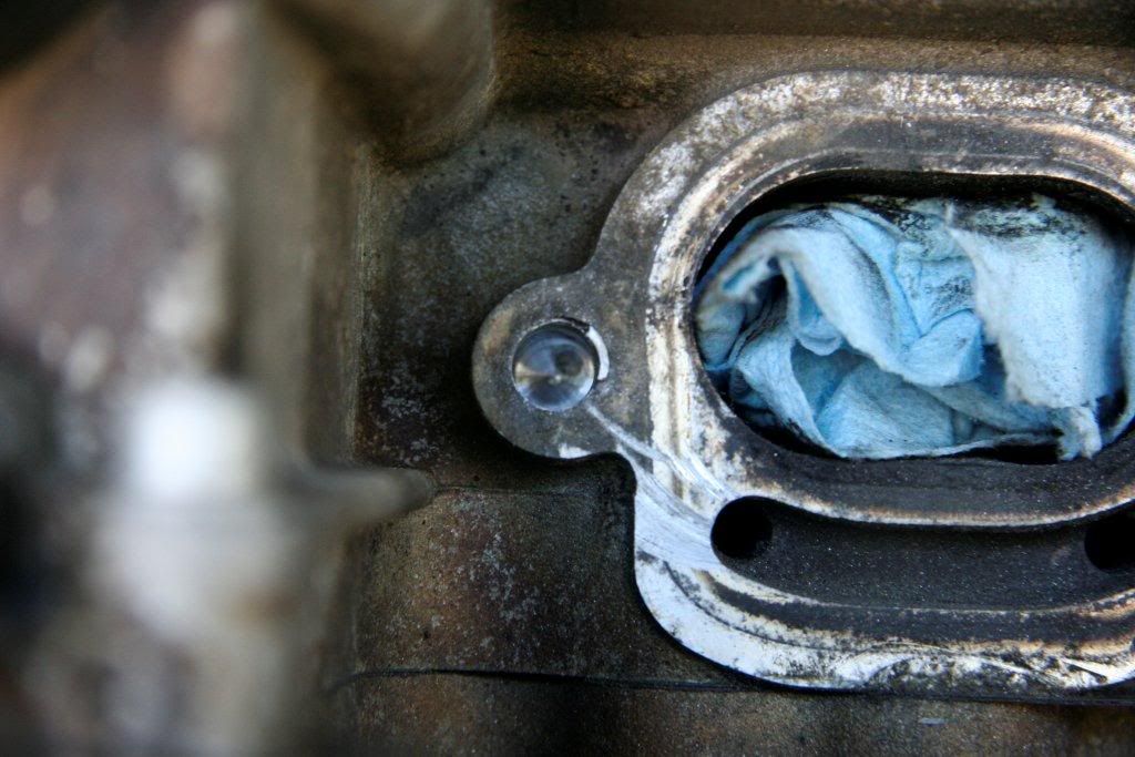
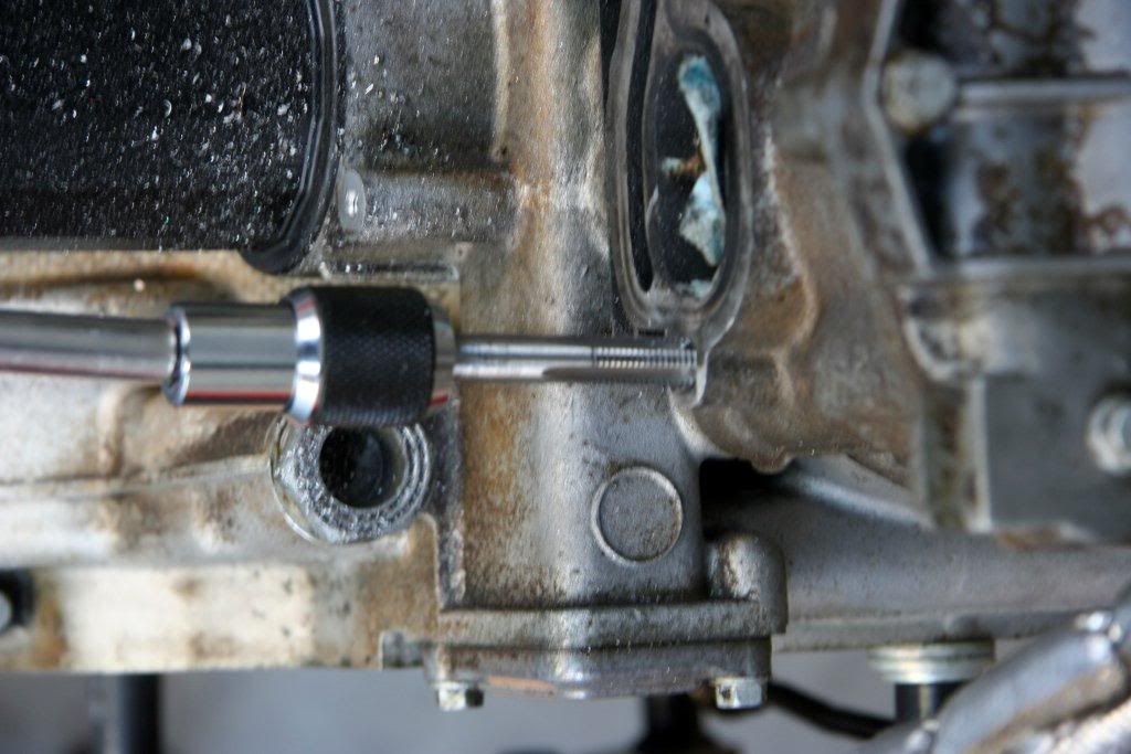
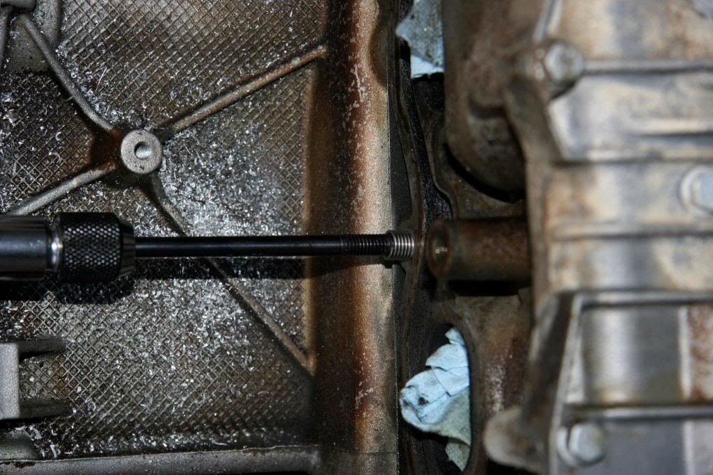
TDC is indicated by a notch on the pully matching a mark on the crankcase as shown in the photo below:
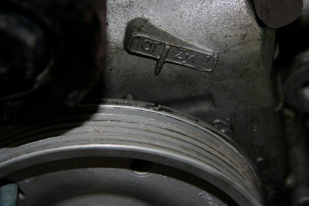
you can 'lock' TDC at the crank by inserting an 8mm bolt through the hole on the pulley marked OT. it will slide into a recepticle on the crankcase as shown in this photo:
.
|
|
|
|
|
10-07-2010, 04:57 AM
|
#70
|
|
Registered User
Join Date: Sep 2004
Location: Atlanta
Posts: 1,820
|
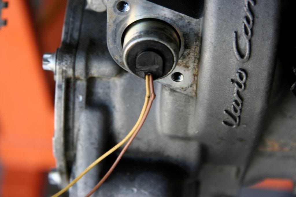
now we should have the motor at TDC. we need to make sure we're at TDC compression before we proceed. to do this, look at the notch in the intake cam we uncovered (this will only have ONE notch in it). it should be pointing OUTWARD like this:
if it is pointing inward, rotate the motor 360 degrees to TDC again. now the notch will be pointing outward.
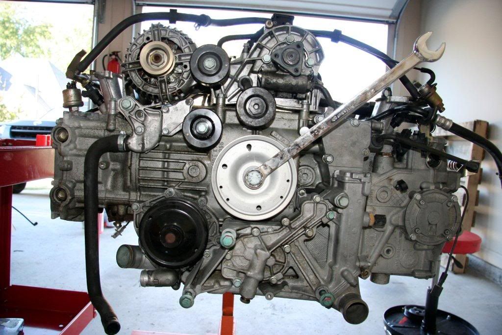
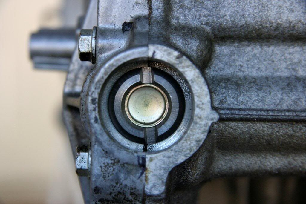
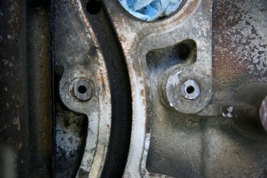
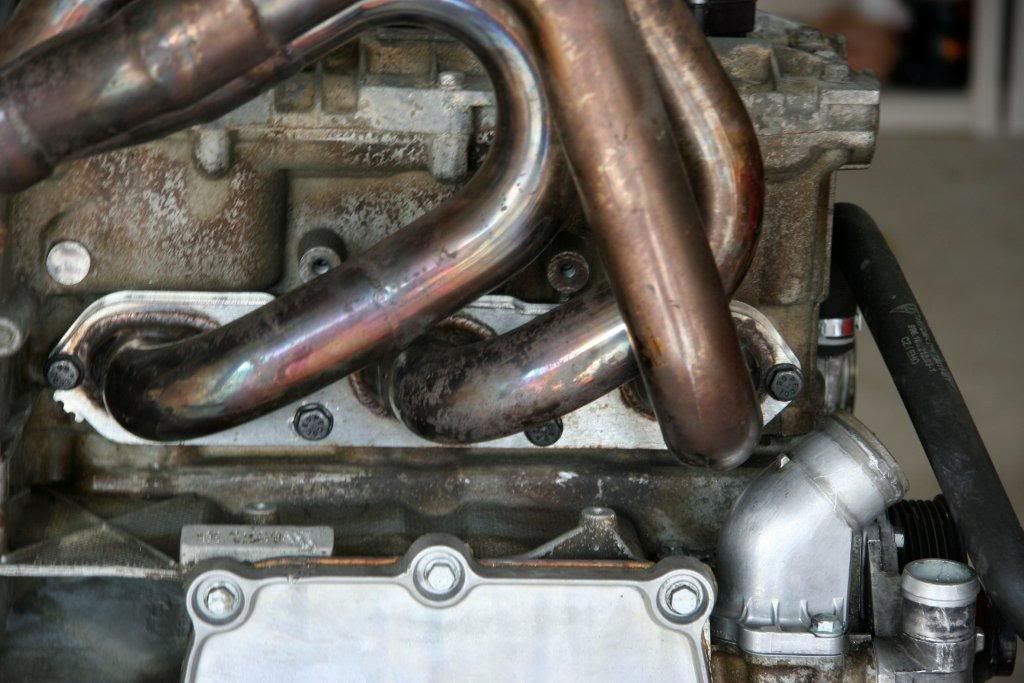
now we will check / set the timing on Bank 1. look at the end of the exhaust cam on bank 1. if the engine is timed properly, the notches will be straight up and down; perfectly parallel to the seam between the head & the valve cover:
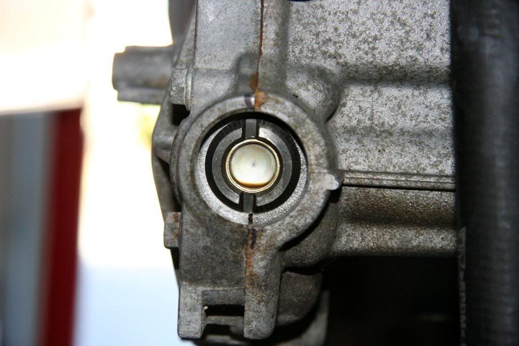
if your timing is off, the notches won't line up; they'll look like this:
if your timing is off, now we need to set it. rotate the engine about 1.5 full rotations. as you approach TDC on the second rotation, check the timing marks. keep rotating the engine until the notches on the bank 1 camshaft are perfectly aligned with the head. once you're there, verify you're at TDC compression by looking at the single notch on the intake cam. it should be pointing OUTWARD.
once your timing marks are lined up & you've verified TDC compression, it's time to change the timing.
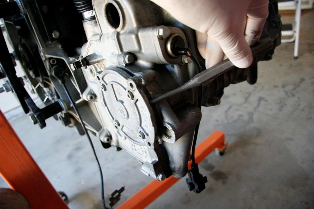
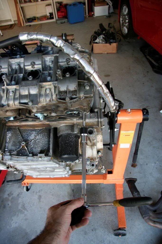
on the back of bank 1, put a match mark onto the oil scavenge pump (THIS IS IMPORTANT). remove the 10mm bolts and gently tap out the scavenge pump.
scavenge pump:
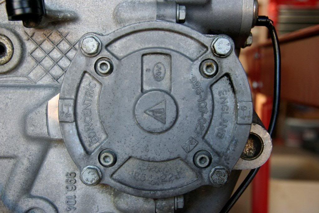
match mark:
tap it out:
now what you should see is this:
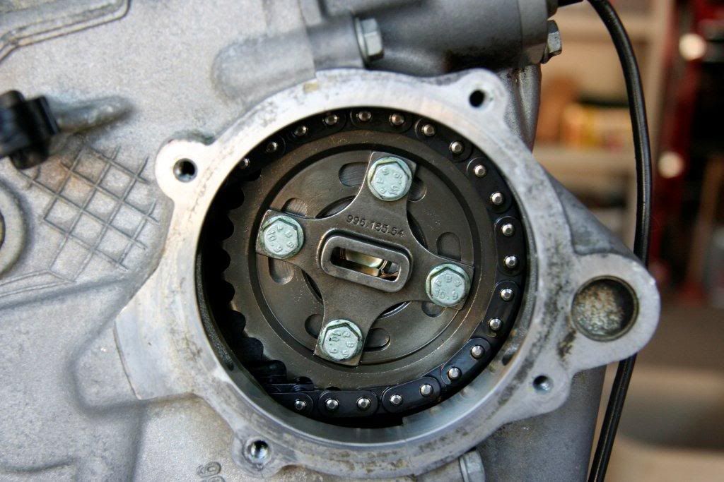
this is the camshaft sprocket. it is adjustable. loosening the four bolts will decouple the camshafts from the crankshaft, allowing you to alter the timing. LOOSEN, but don't remove, the four bolts. rotate the crankshaft to TDC (it's ok if you rotate the motor a tad backward). tighten the four bolts & check the timing notches on the bank 1 camshaft. if you are:
1) at TDC compression (intake cam index notch facing OUTWARD)
2) your bank 1 timing notches are lined up with the head
you have timed bank 1. don't re-install the scavenge pump yet; we'll get there.
now we need to time bank 2. to do this, we need to be at TDC exhaust. rotate the crank ALMOST one full rotation. as you finish the rotation, check the bank 2 timing notches. we want to get them perfectly lined up.
once they're lined up, verify we're near TDC EXHAUST. look at the end of the intake cam, the notch should point INWARD like this:
once you've verified this & bank 2's camshaft is lined up properly, put TWO (this is important) match marks on the bank 2 scavenge pump. we do this because we don't want to get the scavenge pumps mixed up. it's possible to install them upside down & they won't work. by placing two match marks on bank 2's scavenge pump, we can both line it up AND identify which bank it goes into just in case we get confused.....
now, pull the bank 2 scavenge pump and LOOSEN the sprocket bolts. rotate the engine to TDC and tighten the bolts.
now rotate the engine three full rotations to TDC and verify cam timing on bank 1. rotate another 360 degrees and verify cam timing on bank 2.
if all is well, we can begin reassemlby.
first, we are going to remove the cam sprocket bolts ONE AT A TIME, apply loctite, and torque to spec (10.5 ft-lb + 10% to account for loctite = 11.5 ft-lb). BE CAREFUL, DO NOT DROP A BOLT INTO THE ENGINE.
once the cam sprockets are installed, replace the scavenge pumps with new o-rings (lube w/ engine oil first!). install new microencapsulated bolts, and torque to spec (8.5 ft-lb).
tap in new green cam covers with a hammer. no need to add sealant.
you are now done! relax & finish reassembly. drive your car
|
|
|
|
|
10-07-2010, 08:51 AM
|
#71
|
|
Registered User
Join Date: Sep 2004
Location: Atlanta
Posts: 1,820
|
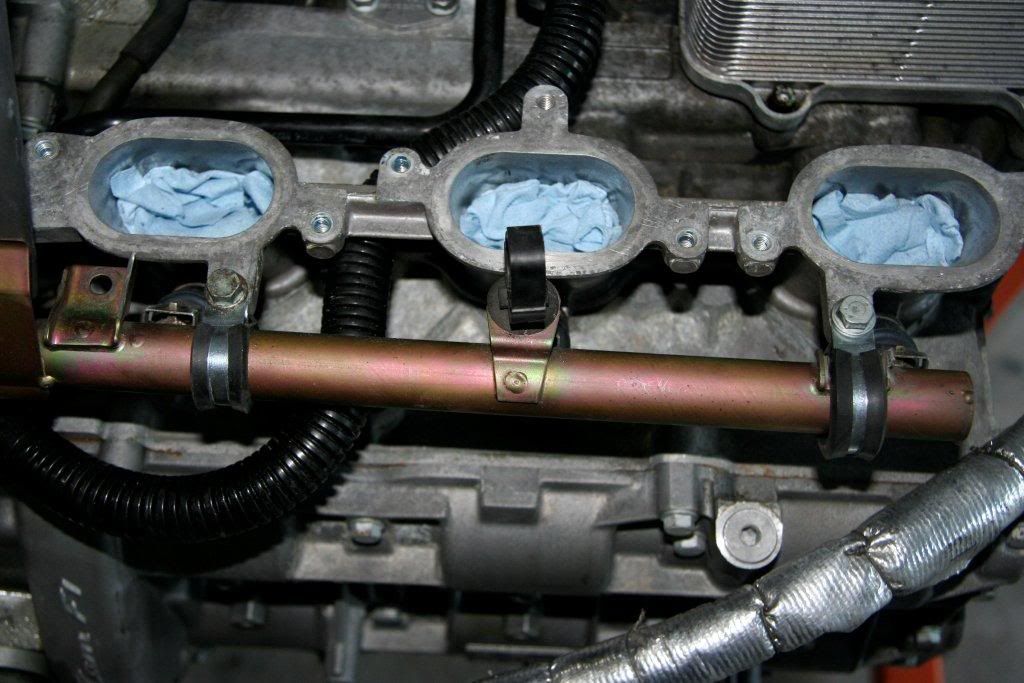
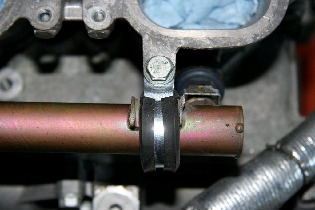
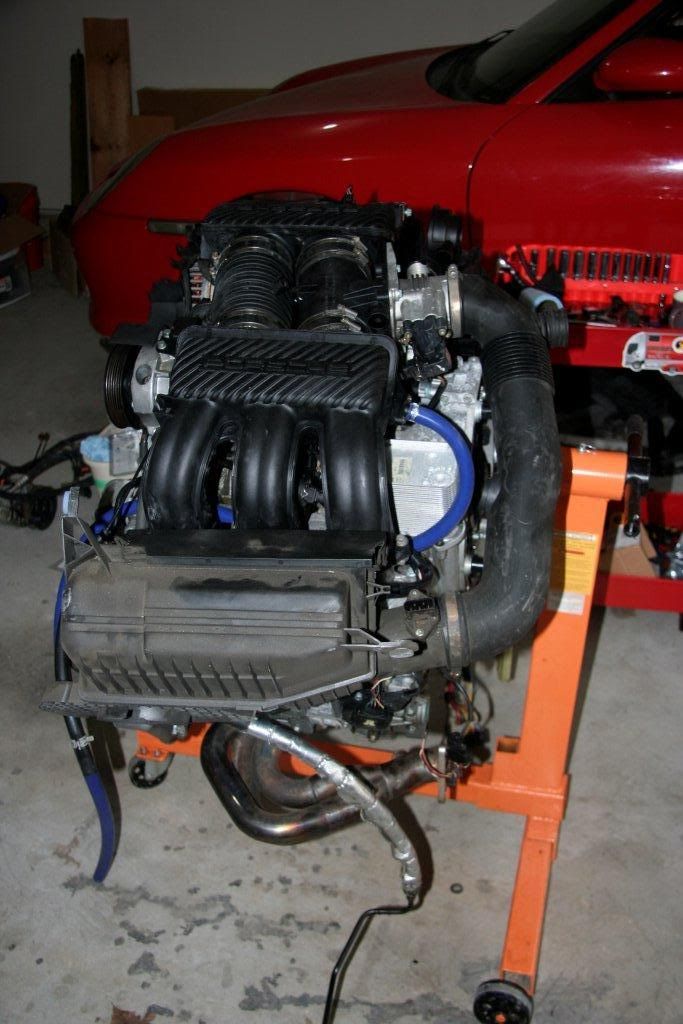
Fuel Rail
a lot of people use Aeroquip fittings & hose to mount the 996 fuel rails into the boxter. i went the other route & mounted the boxster rails to the 996. pretty simple; requires cutting off a couple of mounting tabs & fitting the rails using compression clamps. piece of cake.
two of the original mounting tabs lined up nicely, but didn't allow enough depth to the injector mounting IMO. i felt comfortable with them a bit deeper in the ports.
i used 3/4" compression clamps for three areas & a 1" compression clamp with a little rubber shim on the last. works like a champ; everything is nice & tight.
|
|
|
|
|
10-07-2010, 01:42 PM
|
#72
|
|
Registered User
Join Date: Mar 2008
Location: Oklahoma City
Posts: 1,209
|
I love Adel clamps. They're all we used when building jet engines, from wire harnesses to fuel/hydraulic lines. I seem to remember that I might have a few lying around my toolbox and scrounge bucket. 
__________________
Sadly on the outside looking in.
"Drive it like the Doctor ordered"
|
|
|
|
|
10-15-2010, 12:33 PM
|
#73
|
|
Registered User
Join Date: Dec 2009
Location: Orange County, CA
Posts: 2,013
|
Quote:
|
Originally Posted by insite
probably won't get to work on it again until the 16th.
|
A friendly reminder, today is the 15th....!
so, get back to work and Please share your notes..ha!
.
|
|
|
|
|
10-25-2010, 10:43 AM
|
#74
|
|
Opposed to Subie Burble
Join Date: Mar 2007
Location: Central CT
Posts: 1,197
|
insite, any updates here for us dedicated readers? :dance:
__________________
-O/D
1997 Arctic Silver Boxster, 5-spd
IMSR + RMS
Robbins glass window top
|
|
|
|
|
11-04-2010, 10:19 AM
|
#75
|
|
Registered User
Join Date: Sep 2004
Location: Atlanta
Posts: 1,820
|
hi guys, just checking in. i did get a chance to do some work on the 15th; i drilled out & time-serted the broken studs in one of the heads. i took pics, but my PC died. new computer is up and running. been travelling a lot; hope to be back to work on the p-car this weekend. cheers.
kev
|
|
|
|
|
11-30-2010, 05:01 AM
|
#76
|
|
Registered User
Join Date: Sep 2004
Location: Atlanta
Posts: 1,820
|
okay, update time! let's dive right in. when last i posted, i had an issue with some broken head studs. let's start there. these things were completely welded in place; no way to extract other than to drill.
a couple of notes:
1. if you ever have to do this, BUY A GOOD AC DRILL!!! i picked up an awesome Rigid from Home Depot for around $60. it will do a much better, faster job than ANY battery powered drill
2. get good bits! i recommend Irwin cobalt bits.
3. step up SLOWLY in size, or your pilot hole will 'walk' and come uncentered as your bits increase in size. step up in 1/32" increments to be safe. if you're GOOD, you can try 1/16" increments.
4. use a pilot hole guide to center your pilots. i will post the link to the one i bought when i find it. it basically threads onto the protruding stud & lets you dead-center a 1/8" pilot hole.
5. if you have to use a tap, buy some tap sockets. they will let you use an extension from a ratchet instead of a t-handle; this will give you more room.
6. when you get up to the larger sizes just prior to helicoil insert, bolt on the manifold if you can. it will help keep the larger drill sizes centered.
7. use lubricant when you drill & when you tap.
drill pilots:
step up:
step up more:
tap:
helicoil:
result:
this obviously took awhile. FYI, helicoils are awesome. they come in 1/2" deep inserts, but you can stack two, which is what i did in this case.
|
|
|
|
|
11-30-2010, 05:05 AM
|
#77
|
|
Registered User
Join Date: Sep 2004
Location: Atlanta
Posts: 1,820
|
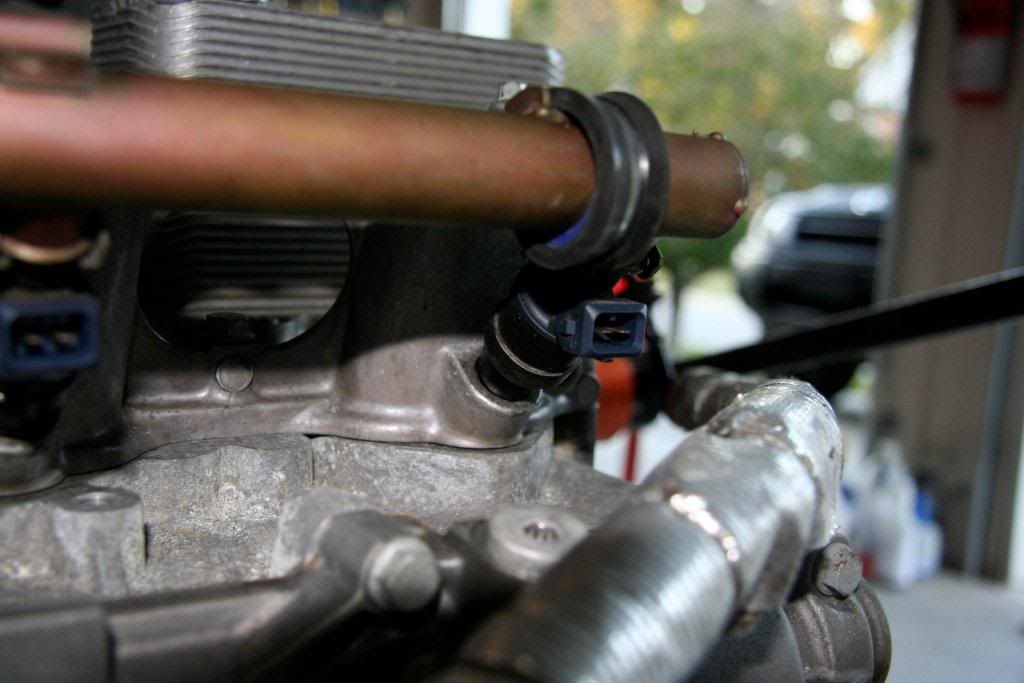
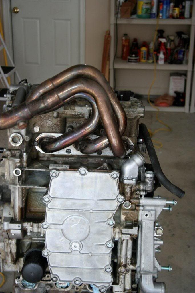
okay, now that we have the exhaust manifolds on, we have a few problems to solve.
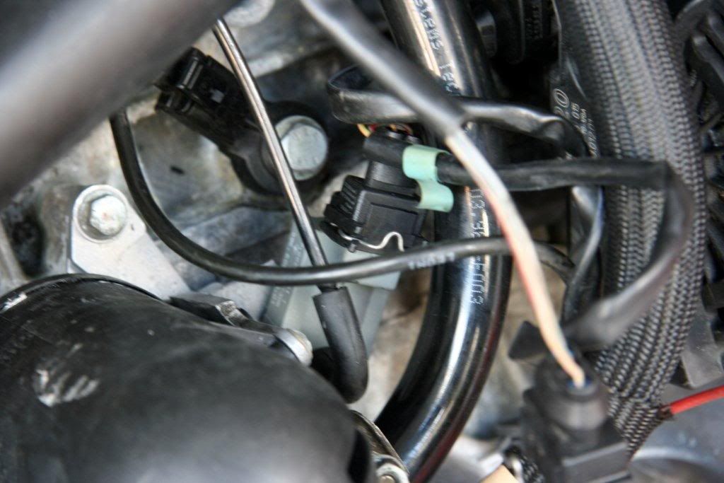
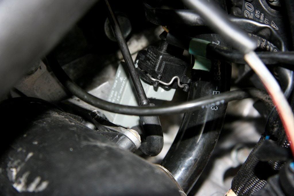
first, the new motor has one variocam actuator with damaged wires. i'd planned on removing the actuator plug & swapping with the one from the old motor, but it turns out you have to remove the valve cover to do this. my solution was to cut off the plug and install some heatshrink tubing. i then soldered the plug back on w/ more heat shrink & some silicone over the penetration.
|
|
|
|
|
11-30-2010, 05:14 AM
|
#78
|
|
Registered User
Join Date: Sep 2004
Location: Atlanta
Posts: 1,820
|
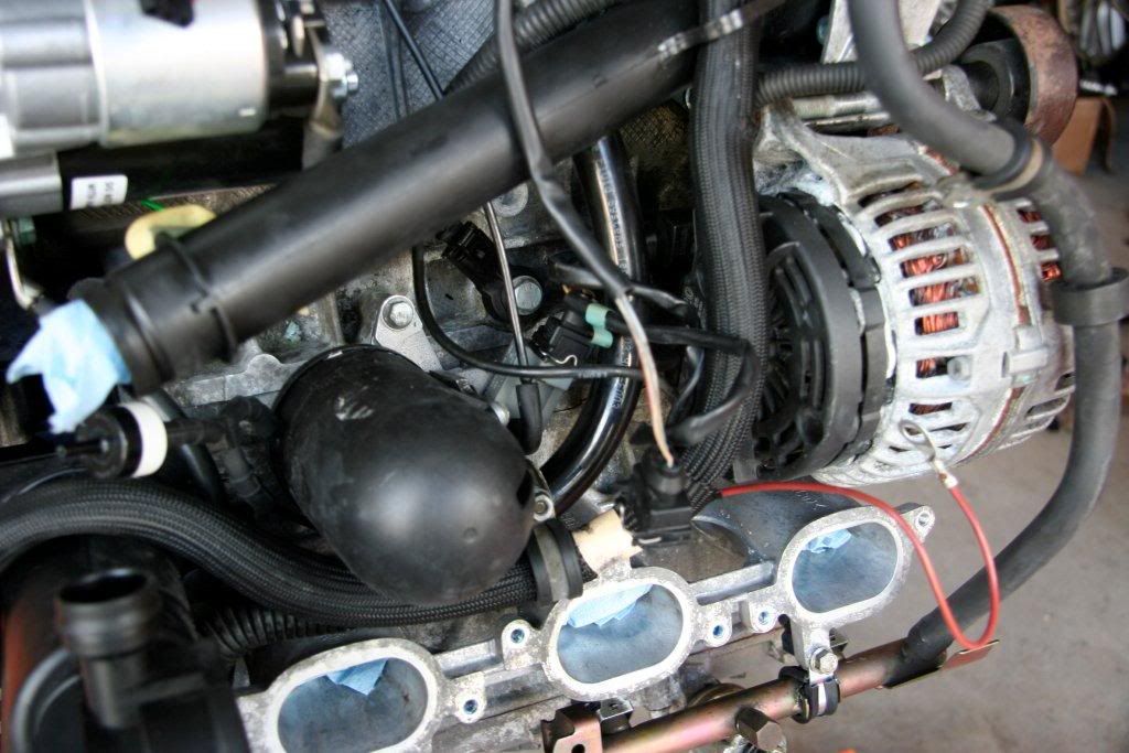
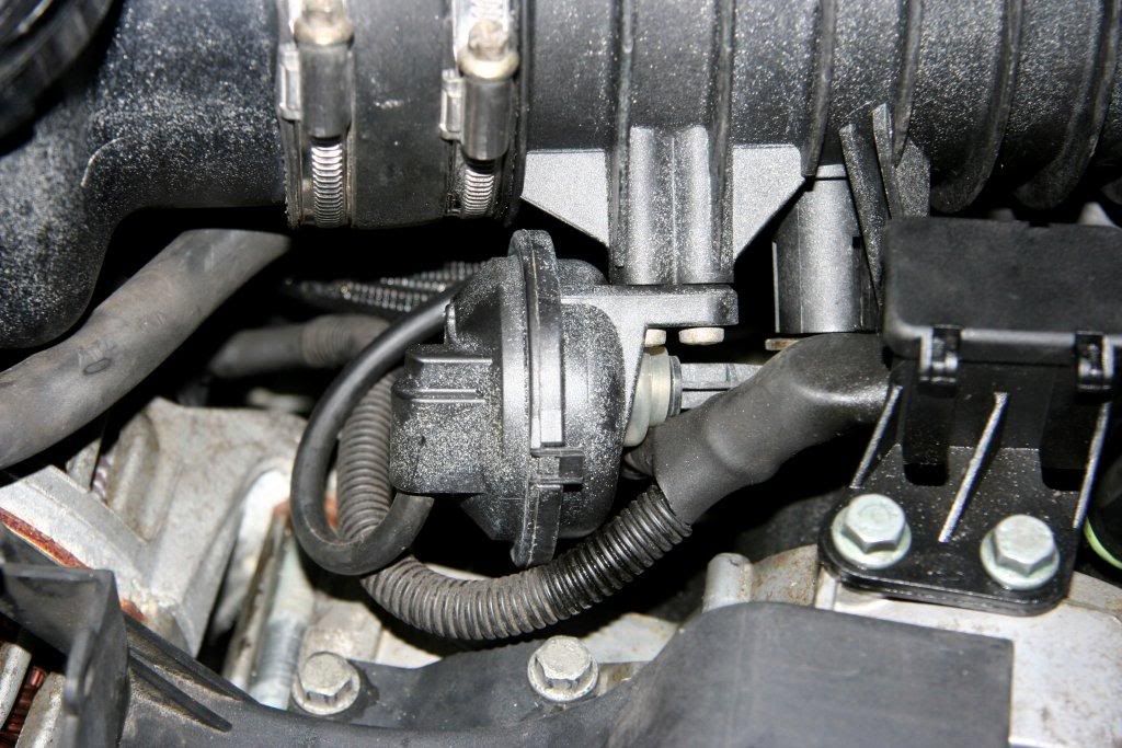
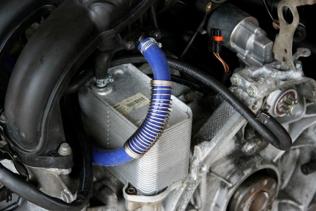
another problem we need to solve is to wire up & plumb the VarioRam valve & its vacuum actuator.
usually, this is done by ADDING a vacuum actuator & running new wires from the actuator to the DME & to a 12V power supply. we are going to do it differently....
since the RoW program i'm using on my DME eliminates the secondary air injection, i am going to use the secondary air injection vacuum actuator to run the VarioRam valve. i installed blocker plates over the secondary air holes on top of the case. i then cut off the vacuum canister bracket from the secondary air stuff i removed from the car. i installed it OVER the blocker in its factory position & used longer bolts.
the vacuum actuator also clips to this bracket. i then ran the vacuum line that USED to control the secondary air valve up to the VarioRam valve.
next, i had to wire it up. good news! use the secondary air plug. all you have to do is move pin 37 to position 59 on the dme plug. much easier than running wires.
|
|
|
|
|
11-30-2010, 06:41 AM
|
#79
|
|
Registered User
Join Date: Sep 2004
Location: Atlanta
Posts: 1,820
|
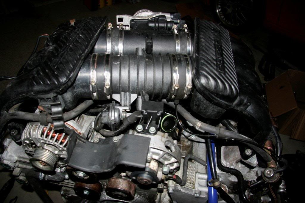
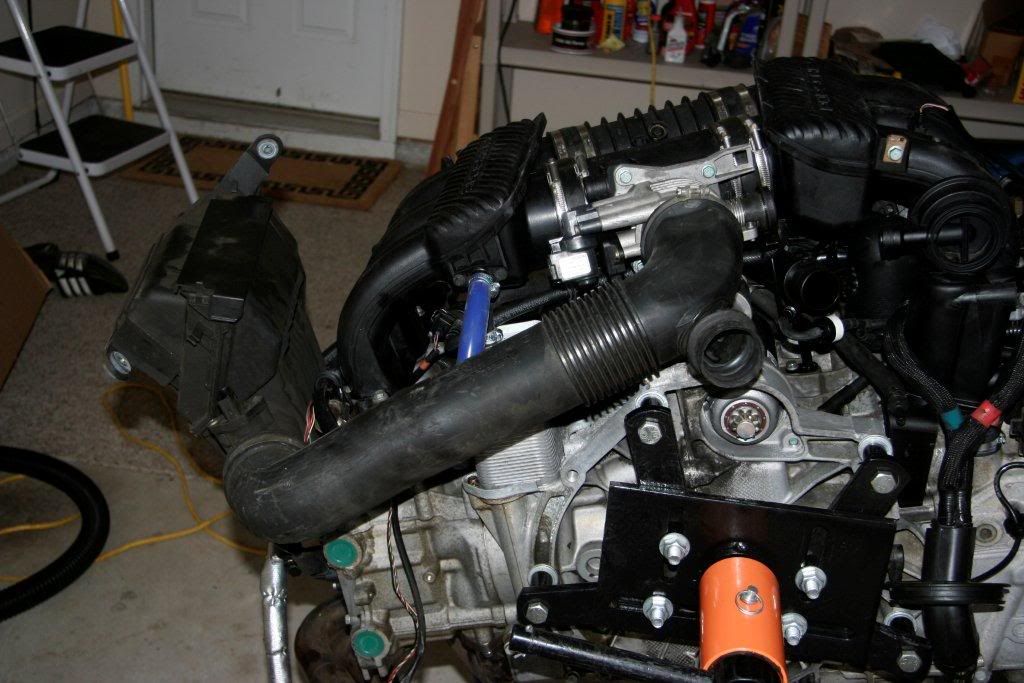
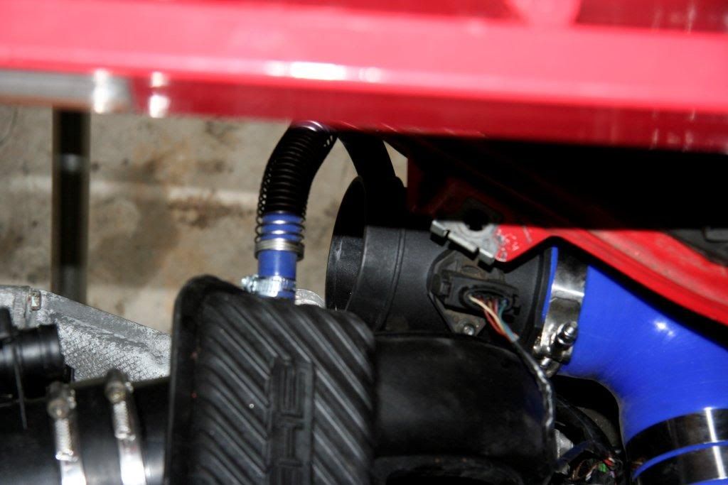
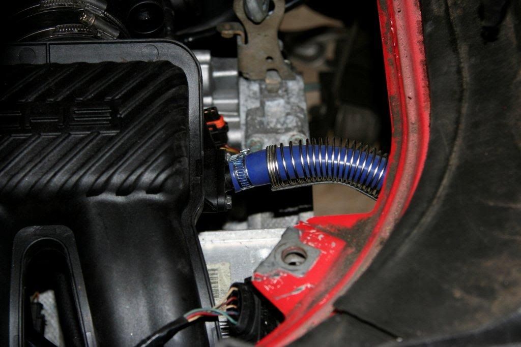
another issue we need to solve is the airbox. the factory airbox plumbing is too narrow for the 3.4L. also, the MAF housing is too narrow. it needs to match the 3.4's diameter in order for the DME program to properly set the air/fuel mixture.
this solution is more or less copied from Cloudsurfer's setup. thanks to him for all of the help here; it took out a lot of guess work for me.
here's the factory airbox setup:
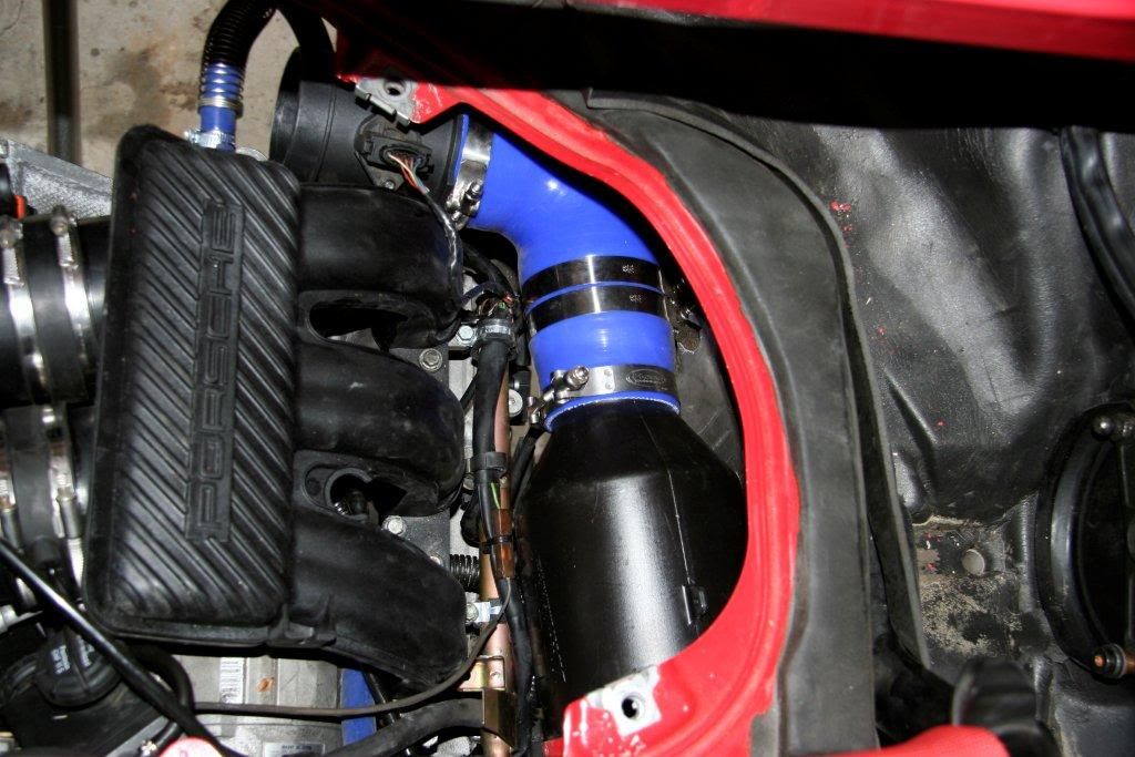
now here's the cloudsurfer setup:

from the airbox by my hand, here is a list of what i used:
1. BMC DIA airbox
2. 3.5" - 3.25" silicone reducer with a 3.5" stainless steel silicone joiner inside
3. 3.5" 90deg silicone elbow
4. BMW 540i MAF housing w/ boxster MAF installed
5. 3.5" silicone straight segment - I ELIMINATED THIS PIECE!!
6. 3.5" - 3.25" silicone reducer (note: there should be a 3.25" stainless steel silicone joiner inside. i couldn't find one, so i used a 3.25" stainless steel BISCUIT CUTTER from kitchenworks.com!!)
7. 3.25" 135deg silicone elbow that's been cut at the proper angle for the throttle body.
|
|
|
|
|
11-30-2010, 08:05 AM
|
#80
|
|
Registered User
Join Date: Sep 2004
Location: Atlanta
Posts: 1,820
|
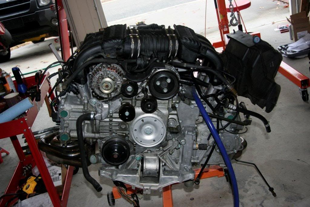
another thing to deal with is the brake booster line. on the 996 manifold, it's on the wrong side. to deal with this, i cut off the hard line that runs up the firewall from under the car. it's possible to cut off the flexible section, exposing a barbed outlet.
to this, i attached some 16mm silicone vacuum hose that i routed underneath the manifold & up to the inlet. originally, i'd flipped the inlet upside down so it pointed downward instead of upward. it turns out that it won't clear my intake plumbing this way, so i put it back into its stock position.
oh yeah, i forgot to mention that the engine is in the car.......and that i've started it.
|
|
|
|
 Posting Rules
|
You may not post new threads
You may not post replies
You may not post attachments
You may not edit your posts
HTML code is On
|
|
|
All times are GMT -8. The time now is 07:47 PM.
| |


 2004 Porsche Boxster S
 1966 VW Bug/Type 1
 1999 Harley-Davidson FLHTC
 Future Volksrod
 Linear Mode


