 11-29-2012, 05:09 PM
|
#1
|
|
Registered User
Join Date: Oct 2012
Location: Wake Forest, NC
Posts: 867
|
IMS Guardian Install - Tips, Tricks, Miscellanea
Having completed my IMS Guardian installation, I thought I'd share a few observations and tips in the event that someone else tackles this project.
First, an overview: I completely changed the order of the various steps in this process.
Flat 6 says to do:
- Disconnect battery negative terminal
- Drain oil
- Remove sump plate and clean
- Install MCD, hand tighten
- Reinstall sump plate
- Torque MCD
- Fill with oil
- Change filter
- Install wiring
- Connect to MCD
Reading the instructions and watching the install video, it seemed to me that the most difficult part of the job was going to be the wiring installation. You have to feed wires from one side of the center stack to the other, and in my car, the HVAC and radio are in the way. Also, the instructions for feeding the main wire through the firewall looked as though that process would be difficult.
So I took a different approach:
- Installed wires in passenger compartment, but didn't connect; ran wire to firewall, hiding behind console and carpeting
- Removed firewall carpeting
- Tried several times to figure out exactly how to feed the wire through to the engine compartment, gave up
- Drilled one inch hole in firewall, installed rubber grommet and fed wire/MCD connector through to engine compartment
- Removed plastic shield beneath engine
- Ran wire to appropriate spot near bottom of engine
- Disconnected neg terminal at battery
- Completed electrical connections in passenger compartment
- TESTED SYSTEM TO MAKE SURE IT WORKS:
- (Connected MCD to harness. Used alligator clips to connect MCD threaded portion to ground. Put negative battery lug back on terminal, didn't tighten. Put key in, turned to ON. IMS-G amber light on; pushed switch, light went red, alarm sounded. Disconnected battery again, unhooked MCD from harness.)
(My logic: why drain the oil BEFORE checking if the system works???)
- Drained oil and removed filter
- Removed sump plate, cleaned
- Installed MCD, hand tightened in sump plate
- Reinstalled sump plate with Loctite 5900, torqued sump plate and MCD to specs. NOTE: MCD should be torqued to 19 ft. lbs.
- Connect MCD to wire harness, tidied up wiring
- Installed new filter, torqued filter housing to spec
- Filled with oil
- Reconnected battery, checked system again
- Reinstalled plastic shield
- Started engine, checked for leaks, checked oil level
- Reinstalled firewall carpeting
For me, and your mileage may vary, this was the right way to approach the job. I suppose if you're experienced with wiring and feeding wires through/around a car's dash, you would have breezed through the wiring process. Me? I took it very slowly, and actually drove the car around town for a week or so with the wiring in the dash in place, but not yet connected.
A observations, photos, and tips...
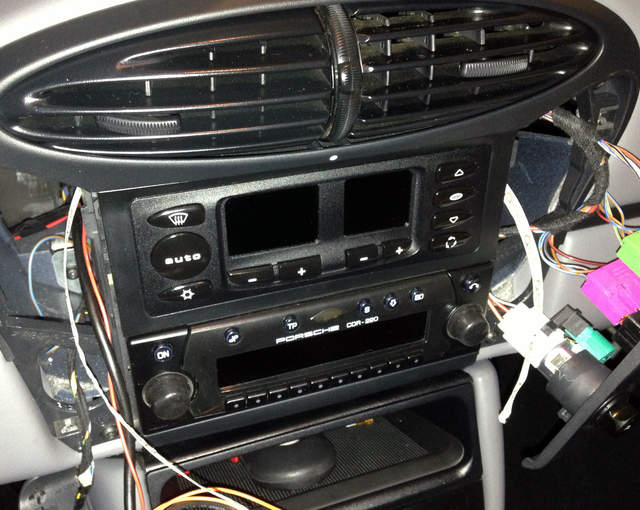
Actually feeding the wire through the dash wasn't difficult, but it could have been. After trying to fish the wires around the HVAC and radio units a few times without success, I had the idea of using a piece of twist tie-type material that was about two to three feet long. I formed it into a circle with a radius of about 3 inches, and then fed it from one side of the center stack to the other; here you can easily see both ends:
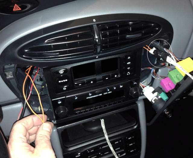
I then taped the 2 wires which need to go from one side to the other to the twist tie material, and fed the wires through. You can see the electrical tape securing the wires to the twist tie material in the circle to the right:
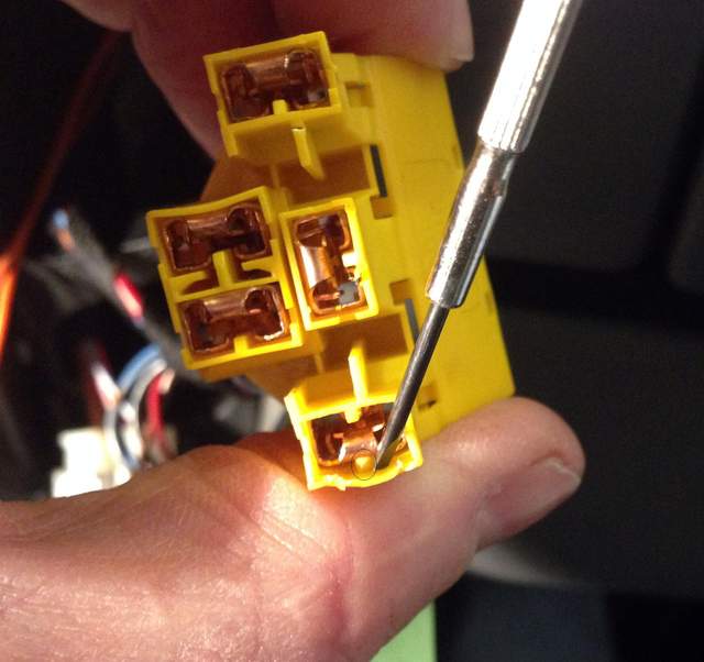
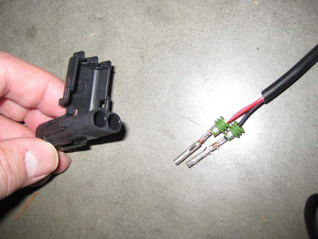
Oh - another thing: the instructions and the IMS-G video show how to remove the wire at #3 in the connector you're to attach the two wires to. Uh, how can I put this? What's shown in the video bears no relationship to reality, at least as regards to the connectors in my car. You have to really examine the spade-type connectors and figure out how they're held in place. In my case, I had to pry the connector up and off a small plastic tab from the FRONT of the connector:
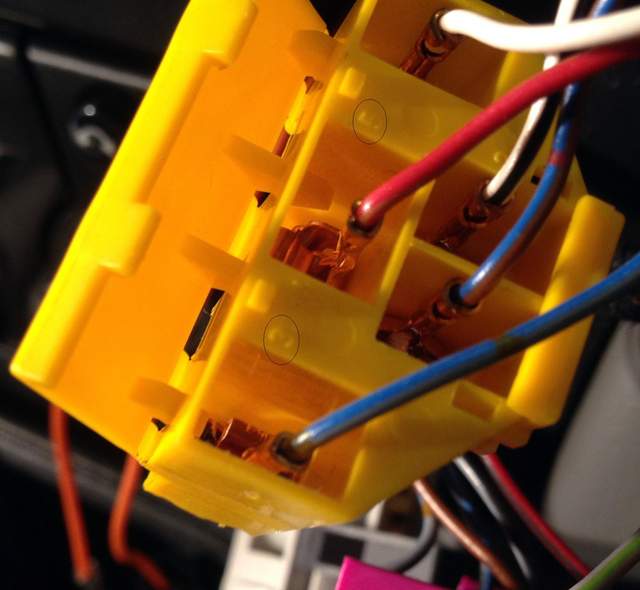
Incidentally, I read somewhere on the interwebs that the wires are not numbered in the connectors. This is not true. See below; #'s 3 & 5 are circled. (Edit: this was on my car; see Jake's comment below)...
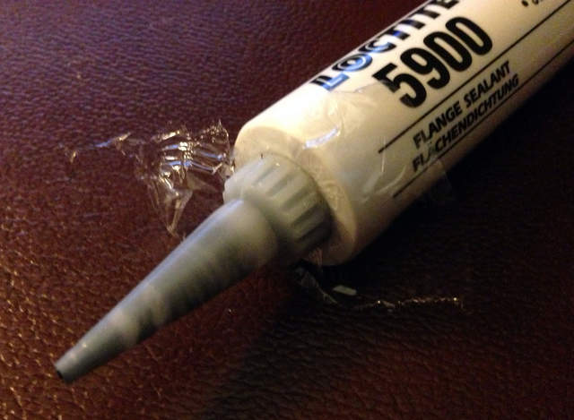
I have to thank Pedro for his help with the install of the wire through the firewall. I tried a few times, but ya gotta be some sort of contortionist/David Blaine-type to feed the wire from the passenger compartment through to the engine compartment. For whatever reason, I struggled with it a lot. Pedro suggested (and provided helpful photos; THANKS!) that I simply punch a hole through the firewall. The best tool for this job is a knockout punch. Thanks to a wonderful mixture of stubbornness and stupidity, I tried to use a 1" drill bit instead. The flutes on that bit are so big that it grabbed and tore the firewall a bit. We ground out the rough edges, and I installed a grommet and used high temp Permatex silicone to provide a seal:
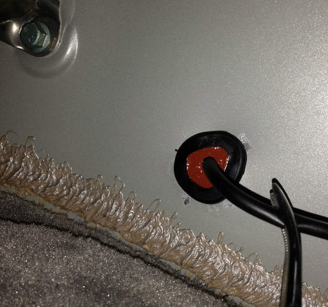
That's a hemostat holding the wire in the center of the grommet, by the way. (Forty years ago, I would have referred to the hemostat as a roach clip. Ha! I'm old!)
The plastic shield beneath the engine, at least in my opinion, needs to be removed in order for you to be able to easily locate the wire in the engine compartment, and for ease in reinstalling the sump plate. No biggie; it was an opportunity to clean it and treat it with some 303 protectant. I am NOT obsessive compulsive!!!!
If you've looked at the IMS-G instructions, you've undoubtedly noted that you can't torque the MCD (the Magnetic Chip Detector, aka your new drain plug with wires sticking out the side) unless you have a special socket. I couldn't find it at the LN Engineering site, and Pelican doesn't carry it, as far as I could determine. So I took a 26mm socket to the guy who runs our Tool Room at work, and he milled a slot in it with a Bridgeport milling machine (the slot is deeper than it needs to be, my bad):
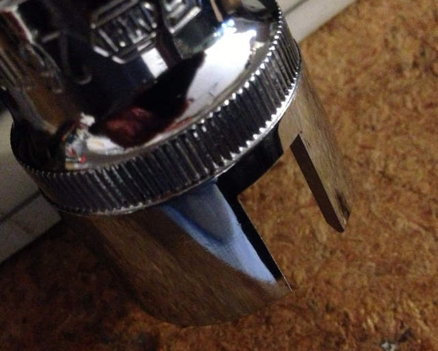
The socket worked absolutely great. Cost? What else? A dozen donuts.
One thing I didn't bother taking a picture of: to keep the wiring in the fuse box neat, I used one of those hobbyist-type glue guns to locate the wire. It keeps the wire away from the tabs on the cover, a good thing.
Wrapping up...
All in all, I'm happy with the install and the kit itself. The components are clearly of high quality. The instructions could benefit from a little attention by a professional tech writer. Failing that, I'd suggest someone who's never done the job do it at Jake's shop, and whoever's responsible for the instructions watch carefully and take notes. My understanding is that the instructions have been upgraded, and as mentioned in another post, I didn't receive the latest version when I ordered from Pelican - hopefully the instructions addressed some of the points mentioned here.
The alarm isn't particularly loud, but knowing myself, I'll glance at the indicator light once in a while. The IMS-G will provide some real peace of mind until I do the bearing retrofit at some point in the future.
Hope this helps someone else!
__________________
2000 Boxster S, 6 speed, Sport Package, Litronics, LED tail lights, LNE IMS-B, OBC, Skybreaker wind deflector, Arctic Silver/Graphite Grey
Last edited by kjc2050; 11-17-2013 at 03:39 PM.
|

|

|
|
11-29-2012, 05:57 PM
|
#2
|
|
Registered User
Join Date: Nov 2012
Location: Raeford, NC
Posts: 11
|
Thanks for the post. I just bought a 2003 S with low miles and the guardian is going to be one of my first upgrades.
|
|
|
|
|
11-29-2012, 07:26 PM
|
#3
|
|
Registered User
Join Date: May 2012
Location: Northern California
Posts: 319
|
This is a great DIY write up!!
|
|
|
|
|
11-29-2012, 09:14 PM
|
#4
|
|
Engine Surgeon
Join Date: Aug 2008
Location: Cleveland GA USA
Posts: 2,425
|
That is very good.. I might want to rob some of this from you!
We have updated the instructions for the new units that are shipping next month but you brought up a couple of points that we overlook because we are too familiar with the product..
BTW not all OEM connectors are marked and some are marked incorrect with pin 1 in the pin 3 position and vice versa.. Makes it very difficult to make an absolute directive.
Glad you are happy with the kit.. :-)
__________________
Jake Raby/www.flat6innovations.com
IMS Solution/ Faultless Tool Inventor
US Patent 8,992,089 &
US Patent 9,416,697
Developer of The IMS Retrofit Procedure- M96/ M97 Specialist
|
|
|
|
|
11-30-2012, 04:48 AM
|
#5
|
|
Registered User
Join Date: Oct 2012
Location: Wake Forest, NC
Posts: 867
|
Quote:
Originally Posted by Jake Raby

That is very good.. I might want to rob some of this from you!
|
Jake: feel free; I'd be honored. I'll post a couple of other tips and perhaps a photo of the fuse box later today. Thanks for making this kit available to Boxster owners.
__________________
2000 Boxster S, 6 speed, Sport Package, Litronics, LED tail lights, LNE IMS-B, OBC, Skybreaker wind deflector, Arctic Silver/Graphite Grey
|
|
|
|
|
12-01-2012, 04:24 AM
|
#6
|
|
Registered User
Join Date: Oct 2012
Location: Wake Forest, NC
Posts: 867
|
A few additional thoughts...
A few things I forgot to mention in my original post, in no particular order:
- Just my opinion, but completing the wiring in the engine compartment will be MUCH easier if the car is on a lift. Seeing where to locate it, zip tying it in place, etc. - these things are possible when you're lying on a creeper with the car 16" or so off the ground, but if there's any way you can get it on a lift for this part of the project, life will be much more enjoyable. I did everything else with the car on jack stands, but when we drilled the hole in the firewall and routed the wire, it was on a lift...
- Use the Loctite sparingly... you need to lay down a bead that's 1 to 1.5mm wide. That's about .05" A little goes a long way. There's NO reason to go overboard. BTW, the the 50mm tube contains way more than you'll need for this job. When everything was buttoned back up, I cleaned out the applicator spout, put a small piece of plastic wrap over the opening of the tube, and then screwed the applicator back on. There was plenty left over for future use.
- A nit: the written instructions tell you to remove the plastic baffle from the sump plate before cleaning the plate. They never indicate that you're to reinstall the baffle. You need to do this. (Fortunately, the video shows the baffle on the plate when the sump plate is being reinstalled.)
- A photo of the wire in the fuse box; circles indicate where I used a little hot melt glue to secure it (sorry, ugly pic):
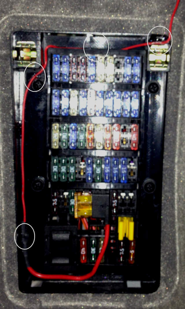
- Feeding the power lead to the fuse box: there's a spot to the upper left of the LH switch panel port that's perfect for this. You don't have to feed the wire forward, deeper into the dash, and then down. Just look to the left side of the opening when you remove the LH switch panel (on LH drive cars).
- Finally, when I torqued the MCD, the difference between hand tight and torqued to 37 ft. lbs. was nowhere near a "quarter turn." My advice? Get a socket modified or buy one from LN, and use a torque wrench.
April 2013 EDIT: NOTE: per Jake Raby, the MCD should be torqued to 19 ft. lb., NOT 37!! Torquing to 37 will damage the MCD.
Good luck!
__________________
2000 Boxster S, 6 speed, Sport Package, Litronics, LED tail lights, LNE IMS-B, OBC, Skybreaker wind deflector, Arctic Silver/Graphite Grey
Last edited by kjc2050; 04-19-2013 at 04:27 AM.
|
|
|
|
|
05-29-2013, 03:44 AM
|
#7
|
|
Registered User
Join Date: May 2013
Location: New Zealand
Posts: 15
|
Thanks good post..I finished my IMS Guardian install today. Did it in 4 stages and combined it with some routine maintenance. I drove the car regularly between each stage and it took me about about 3 weeks total time, about half a day each stage.
Stage 1 MCD install, sump inspect, oil and filter change, used oil analysis.
Stage 2 Switch install and connect wires to fuse box.
Stage 3 Thread wires into engine compartment, air filter change, power steering fluid check.
Stage 4 Connect wires to MCD unit secure wiring under car, cabin filter change.
All good, car running well. Thanks Jake for a great idea and kit for monitoring our engines.
__________________
2004 Boxster S
Suzuki Grand Vitara 2.5LV6 / Nissan Elgrand 3.3L V6
Ducati 900SSie / Ducati Pantah 600SL (race bike)
|
|
|
|
|
10-27-2013, 08:17 AM
|
#8
|
|
Registered User
Join Date: Jan 2007
Location: BC
Posts: 1,355
|
What's the proper position for the red, white and black wires in the weatherproof connector? Coloured wires were scotch-taped to the connector, presumably as indicators, but they fell out when I opened the package. No indication in the video or manual.
__________________
2001 Boxster, 5 spd, Seal Grey
|

|
|
|
10-27-2013, 10:09 AM
|
#9
|
|
Engine Surgeon
Join Date: Aug 2008
Location: Cleveland GA USA
Posts: 2,425
|
Quote:
Originally Posted by clickman
What's the proper position for the red, white and black wires in the weatherproof connector? Coloured wires were scotch-taped to the connector, presumably as indicators, but they fell out when I opened the package. No indication in the video or manual.
|
Email info@flat6innovations.com and we will reply with a directive.
__________________
Jake Raby/www.flat6innovations.com
IMS Solution/ Faultless Tool Inventor
US Patent 8,992,089 &
US Patent 9,416,697
Developer of The IMS Retrofit Procedure- M96/ M97 Specialist
|
|
|
|
|
11-01-2013, 03:20 PM
|
#10
|
|
Registered User
Join Date: Jan 2007
Location: BC
Posts: 1,355
|
For completeness, here is the answer I got from Mr Raby and crew:
The black wire will insert into the "B" embossed side of the connector (look hard - it's there). The red wire with the white trace will insert into the "A" embossed side of the connector.
If you look at the wires on the other plug, match the black wire to the black wire.
__________________
2001 Boxster, 5 spd, Seal Grey
|
|
|
|
|
11-01-2013, 05:20 PM
|
#11
|
|
Registered User
Join Date: Oct 2012
Location: Wake Forest, NC
Posts: 867
|
Norm, were you able to disconnect the wire at #3 in the connector?
__________________
2000 Boxster S, 6 speed, Sport Package, Litronics, LED tail lights, LNE IMS-B, OBC, Skybreaker wind deflector, Arctic Silver/Graphite Grey
|
|
|
|
|
11-01-2013, 10:17 PM
|
#12
|
|
Registered User
Join Date: Jan 2007
Location: BC
Posts: 1,355
|
Yes. I was looking at your picture the wrong way at first. ")
One thing, though: you used the end connector, numbered 3 in your pic. I used the one beside and up from it, with the blue / brown wire, cause the video said to use the same physical location that they show. Hopefully it'll work...
__________________
2001 Boxster, 5 spd, Seal Grey
Last edited by clickman; 11-01-2013 at 10:23 PM.
|
|
|
|
|
11-02-2013, 05:22 AM
|
#13
|
|
Registered User
Join Date: Oct 2012
Location: Wake Forest, NC
Posts: 867
|
Quote:
Originally Posted by clickman
One thing, though: you used the end connector, numbered 3 in your pic. I used the one beside and up from it, with the blue / brown wire, cause the video said to use the same physical location that they show. Hopefully it'll work...
|
Hmm... dunno. Let me know how you make out. FWIW, mine works fine.
__________________
2000 Boxster S, 6 speed, Sport Package, Litronics, LED tail lights, LNE IMS-B, OBC, Skybreaker wind deflector, Arctic Silver/Graphite Grey
|
|
|
|
|
11-02-2013, 07:31 AM
|
#14
|
|
Engine Surgeon
Join Date: Aug 2008
Location: Cleveland GA USA
Posts: 2,425
|
ONLY use the physical location as illustrated i the video. The reason for this is the connectors are not always correct, even though they are OEM Porsche connectors used for the seat heater switch.
__________________
Jake Raby/www.flat6innovations.com
IMS Solution/ Faultless Tool Inventor
US Patent 8,992,089 &
US Patent 9,416,697
Developer of The IMS Retrofit Procedure- M96/ M97 Specialist
|
|
|
|
|
11-02-2013, 10:52 AM
|
#15
|
|
Registered User
Join Date: Oct 2012
Location: Wake Forest, NC
Posts: 867
|
Quote:
Originally Posted by Jake Raby
ONLY use the physical location as illustrated i the video. The reason for this is the connectors are not always correct, even though they are OEM Porsche connectors used for the seat heater switch.
|
What video? The one on the installation page is private: IMS Guardian Installation
__________________
2000 Boxster S, 6 speed, Sport Package, Litronics, LED tail lights, LNE IMS-B, OBC, Skybreaker wind deflector, Arctic Silver/Graphite Grey
|
|
|
|
|
11-02-2013, 11:00 AM
|
#16
|
|
Engine Surgeon
Join Date: Aug 2008
Location: Cleveland GA USA
Posts: 2,425
|
Quote:
Originally Posted by kjc2050
|
Each kit comes with an install DVD in the box.
See this page for the video:
Installation and Warranty | IMS Guardian
__________________
Jake Raby/www.flat6innovations.com
IMS Solution/ Faultless Tool Inventor
US Patent 8,992,089 &
US Patent 9,416,697
Developer of The IMS Retrofit Procedure- M96/ M97 Specialist
|
|
|
|
|
11-10-2014, 08:07 AM
|
#17
|
|
Registered User
Join Date: Nov 2014
Location: Switzerland
Posts: 3
|
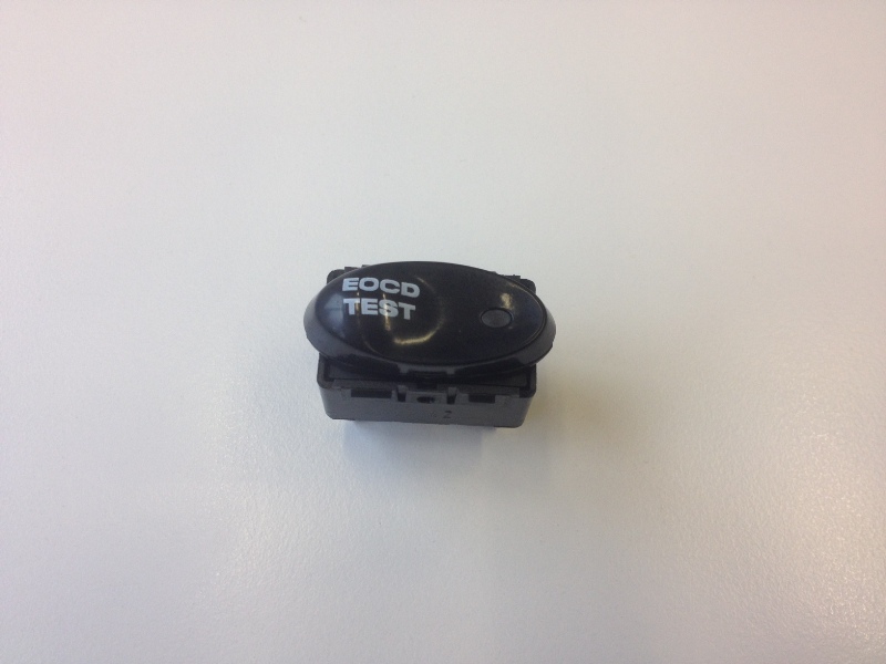
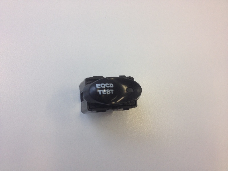
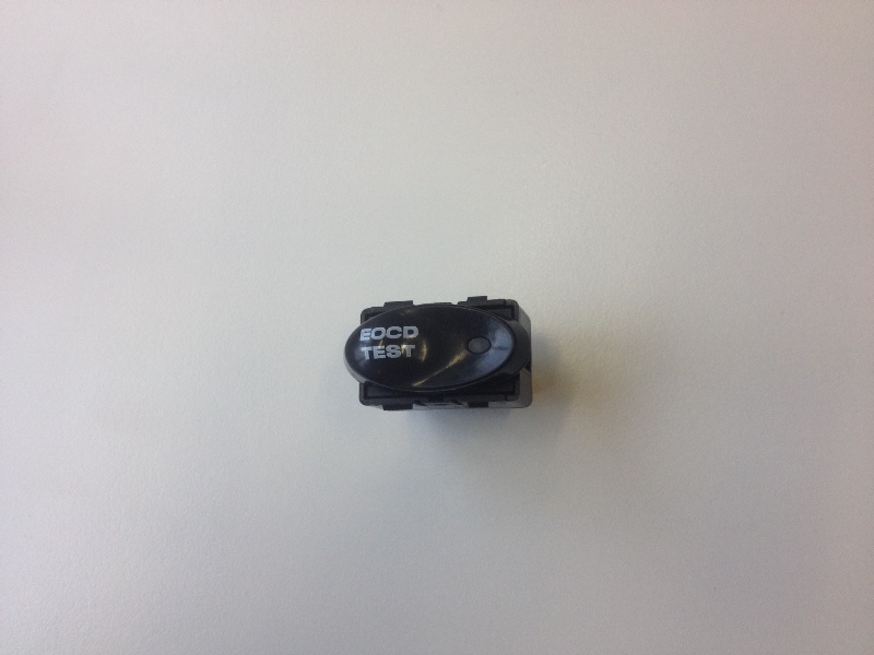
Great post, now can ayone tell me where to rout the cable through in a 986 Boxster 2004 model without drilling a 1" hole? By the way I didn't like the sticker that came with the kit to mark the switch. I pad printed the switch to look as factory as possible. I didn't find the proper font but it still looks quite good. I called it EOCD for Engine Oil Chip Detector.
Can anyone tell me the best way to bring the cable from the interior to the engine compartment?
Thanks
Dom
|
|
|
|
|
11-10-2014, 08:49 AM
|
#18
|
|
Registered User
Join Date: Oct 2012
Location: Wake Forest, NC
Posts: 867
|
Just my $ .02, but I prefer the plain switch to that. You know what the switch is for, why does it need to be labeled?
As for your question, perhaps Jake Raby or Pedro will comment, but if you can't do it per the IMS-G instructions, I think you'll have to use a drill.
__________________
2000 Boxster S, 6 speed, Sport Package, Litronics, LED tail lights, LNE IMS-B, OBC, Skybreaker wind deflector, Arctic Silver/Graphite Grey
|
|
|
|
|
11-11-2014, 12:48 PM
|
#19
|
|
Registered User
Join Date: Jan 2007
Location: BC
Posts: 1,355
|
I followed the method in the video, which makes it look much easier than it is, by my experience. I couldn't figure out how to remove or loosen the plastic fixture in the corner and had to fight my way past it...
__________________
2001 Boxster, 5 spd, Seal Grey
|
|
|
|
|
11-11-2014, 01:20 PM
|
#20
|
|
Registered User
Join Date: Jan 2007
Location: BC
Posts: 1,355
|
Make sure the wire from the oil pan plug sensor is fastened down well. Mine must have been whipping around in the wind, as the wire insulation is separating and splitting at the plug. Trying silicone caulking... 
__________________
2001 Boxster, 5 spd, Seal Grey
Last edited by clickman; 11-12-2014 at 07:51 AM.
|
|
|
|
 Posting Rules
|
You may not post new threads
You may not post replies
You may not post attachments
You may not edit your posts
HTML code is On
|
|
|
All times are GMT -8. The time now is 07:18 PM.
| |


 Boxster S
 Genesis 3.8
 2001 Porsche 986 Boxster
 Linear Mode


