Fan Switch Part List
$32 Defroster Switch, Matte Finish (996-613-134-10-A05)
$25 Omron MY2K-DC12 Latching Relay
$5 ATC Fuse Tap with .250 Male Disconnect
$5 2.8MM Female Wire Terminal
Various Male & Female Disconnects, Butt Connectors and Heat Shrink Tubing
Various Lengths of 16AWG Wire
Optional:
$23 2-Button Batwing (996-552-335-02)
Garage Switch Part List
$47 996TT Targa Switch (996-613-119-10-A05)
Various Male & Female Disconnects, Butt Connectors and Heat Shrink Tubing
Various Lengths of 16AWG Wire
Background
The 986 is equipped with a left and right radiator fan. These fans have two speeds, high and low. The low speed fans come on whenever the AC is turned on, the high speed fans trigger when the
coolant temp hits 215° F or the AC pressure hits a certain level (source RennTech thread). While you could wire a switch to trigger the low or high fans, you can already trigger the low fans by turning on the AC, which is why this modification focuses on triggering the high fan speed.
The point of installing a manual switch is to help cool your 986 before it hits the temperature threshold where the high speed fans would automatically come on. This could include track days where you want extra cooling and do not want to lose horsepower to the AC, or when you are in summer traffic and want to keep the car from heating up.
Installing a manual switch should not override the normal operation of the high or low speed fans, it just lets you trigger them manually. If you leave the switch on when the car is turned off, the fans will automatically turn off after a short delay, and the fans will come on the next time the car is started.
Preparation
Start by disconnecting your battery, and placing a small block over the trunk latch to ensure the trunk does not accidentally close while the battery is disconnected.
If you are installing the switch into the batwing trim piece:
Remove the carpeted trim on the driver and passenger side of the lower center console by grabbing the rear of the carpet and pulling out until the clips release, then slide the trim back and out.
Then remove the leather/leatherette trim on either side of the lower center console by grabbing it from the back and pulling out until the clips release, then slide it forward and off.
You can now remove the batwing by pulling on each side of the trim piece.
While not necessary I wanted room to work, so I also removed both cubbies from my lower center console. Remove the upper one first by pulling it out from each side, then the lower cubby is able to removed the same way.
Step 1 - Wiring the Relays

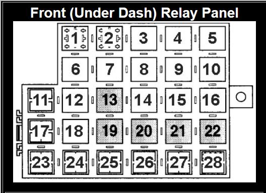
First you want to identify the high speed fan relays. They are located in the driver’s footwell above the fuse panel. The bottom row that is visible has four 53 relays, looking at the diagram the high speed relays are #20 and #22. Remove both relays.

Now take a fuse tap and pliers to bend it to fit Pin 85 on the relay. The fuse taps I purchase required some filing to make them wide enough to over the relay pin. With the fuse tap installed, secure it to the relay. I decided not to use electrical tape because the relays can get quite hot while the car is running and I want to avoid a sticky mess, so I instead opted to secure them with a zip tie which I pulled tight with a pair of pliers. Note that the head of the zip tie is pointing down to make it easier to reinstall next to the other relays.

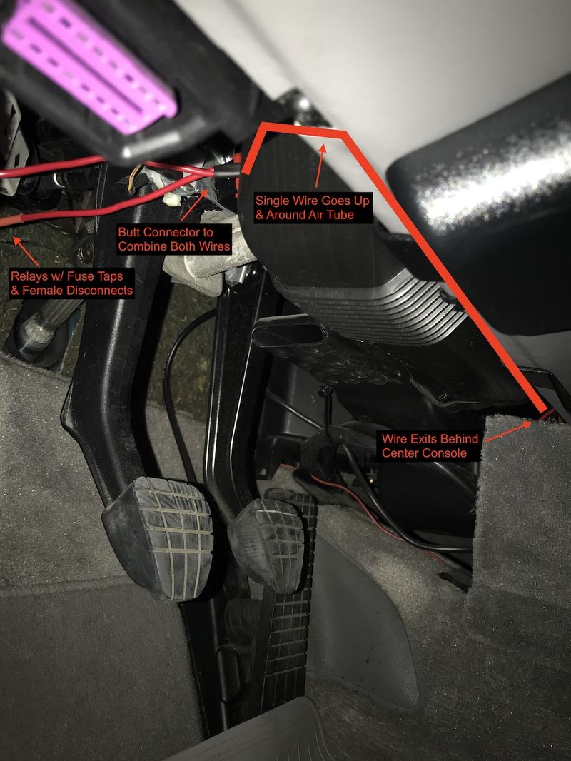
Next take approximately two 6” wires and install two female disconnects on one end of each wire which attaches to the fuse taps, then combine both wires into a single butt connector. On the other side of the butt connect you want a few feet of wire that terminates in a disconnect (male or female depending on how you wire the relay and switch), mine ended with a female disconnect. This is the Pin 85 wire, that will be attached the latching relay later on.

Route the wire to the center console, by pushing it up and around the plastic air tube above the driver’s footwell, then into the lower center console.
Step 2 - Wiring the Switch and Latching Relay
Since I was using the batwing trim piece I started by installing the switch into the batwing. This is tougher than you would think. With the switch in place but not “snapped in” I placed the batwing and switch on the edge of a table with the outside facing up. By using the edge of the table I could rest the batwing on the switch pins but let the batwing hooks which are longer hang off the edge. I think hit the trim piece with my hand until the switch snapped into place. I also placed thin cardboard on the table to avoid it getting scratched by the switch pins. The switch should sit flush with the batwing if installed correctly.
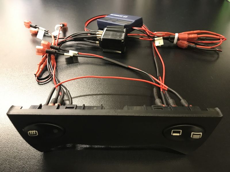
The 2.8MM female disconnects are for the relay pins which are smaller than the switch pins, which accept normal female disconnects. To make the batwing removable, I used male and female disconnects. If you decided to do like me, instead of just hardwiring it into the car without any way to disconnect it, you would end up with four wires that need to be hooked up: Relay Pin 85, 12V Switched Power, Ground, Illumination Power.
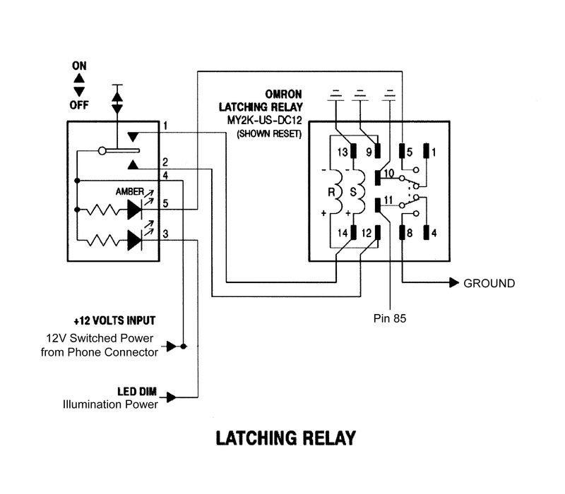
It is rather hard to describe the wiring in text so please review the diagram below.

Switch Pin 1 - Relay Pin 14
Switch Pin 2 - Relay Pin 12
Switch Pin 3 - Illumination Power from dash Defroster Switch Pin 3
Switch Pin 4 - 12V Switched Power from Phone Connector
Switch Pin 5 - Relay Pin 5
Relay Pin 9, 10, 11, 13 - Ground (I used the Phone Connector Ground)
Relay Pin 11 - Pin 85 Wire
Relay Pin 1 & 4 are not used

Notes:
-The Phone Connector 12V Switched power is Green/Black
-The Phone Connector Ground is Brown
-I wrapped the latching relay in some electrical tape to help “cushion” it but that probably isn’t necessary.
-For the 4 Relays Pins that need to be grounded, I connected the wires using butt connectors.
-The illumination power must come from the dash Defroster Switch Pin 3, this switch is wired differently than the others, and using a different source will cause the switch to always be on.
Step 2.5 - Illumination Wiring
I had previously tapped into the cigarette lighter for illumination power and ground, and the original plan was to use the same wiring. In most of the pictures in this guide you can see that the two switches share a wire, which was supposed to be the Illumination wire. However, the defroster switch uses a different signal for illumination than every other switch in the car. So you need to tap into the defroster switch in the dash for the illumination to work properly.
Take a butter knife and insert it into the bottom of the switch panel, then carefully pry the trim piece out, it should unsnap and come free. The wiring harness doesn’t give you much room to work with, but you only need to remove the plug from the defroster switch. I used a flathead screwdriver to get it started, then carefully removed it the rest of the way, being careful not to damage my dash.
As you can see, I chose to use another fuse tap on Pin 3 of the dash Defroster Switch. I secure it with a zip tie, and then ran a wire behind the center console to the lower center console. I removed the radio to route the wire, it may be possible without this step, but it would be difficult. Removing the radio requires inserting radio keys into the lower left and right slots.
 Step 3 - Installing the Batwing & Switch

Slide the latching relay and wiring through the batwing opening. You may not be able to fit the latching relay through the batwing opening, so be prepared to disconnect the relay from the switch and plug it back in. With the wiring in place, connect the four loose wires: the Pin 85 wire that runs to the relays, the illumination power coming from the defroster switch, and the phone connector power and ground.
Test the fan switch by reconnecting the battery and turning your key to the first position (power on), the latching relay requires 12V to operate, so it won’t work with the car off or the battery disconnected. The left side of the switch should trigger the high speed fans, and the amber LED in the switch should illuminate, the right side of the switch will stop the fans.
Snap the batwing into place, and reinstall the lower center console trim in the reverse order.
 The Easy Way
Follow Step 1 to tap the relays, then connect them to a simple on/off switch with the other end grounded to the phone connector or another ground point. You can stick the switch on the bracket under the steering wheel. I originally installed a simple switch this way and it worked fine, but I wanted a more clean and permanent installation.
My last step is to install a 2.5" silver '986" decal on the batwing.

Also, thanks to particlewave for his help figuring out the wiring in
this thread, and RennTech member Sandy that created the latching relay diagram I modified. I also have a copy of this DIY posted to my website.