 05-22-2018, 01:31 PM
|
#1
|
|
There Is No Substitute.
Join Date: May 2007
Location: West Coast
Posts: 3,253
|
Defroster Switch Wiring
I installed a switch to manually trigger my high and low radiator fans last year, but I would now like to finish the job by dash mounting the switch. I am planning to buy a two button 996 batwing, and I would like to use a defroster switch (996-613-134-00-A02). This switch normally has low, high, and off. Which I would like to use for low, high and off for the radiator fans.
The radiator switch works by grounding either the high or low set of fan relays. This thread on Rennlist indicates that the defroster switch is a Type B 2 SPST switch (not sure what that means). I am not an expert on reading electrical diagrams, but my understanding from the diagram is that if I wire the high fans and low fans to pin #3 or #5 and the ground to #4, it should function with one press triggering the low fans, another triggering the high fans, and another press shutting everything off. Is this correct?
What about pins #1 and #2? Would those be used for illumination?
Thanks in advance! -Rick 
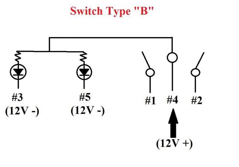
This is the switch wiring from the Bentley manual:
__________________
1999 Ocean Blue Metallic Boxster - blueboxster.com
Last edited by rick3000; 05-22-2018 at 01:34 PM.
|

|

|
|
05-22-2018, 03:11 PM
|
#2
|
|
Custom User Title Here
Join Date: Mar 2012
Location: Ft. Leonard Wood
Posts: 6,169
|
I'm not sure about the fan wiring, but be aware that all 3 switch types are momentary (power is only applied while switch is being pressed) and you may need latching relays.
BTW, SPST = single pole, single throw. When pressed on either side, either connector #1 or #2 will make contact with #4
Being a rocker switch, it could be thought of as a SPDT (single pole, double throw).
https://learn.sparkfun.com/tutorials/switch-basics/poles-and-throws-open-and-closed
Last edited by particlewave; 05-22-2018 at 03:14 PM.
|
|
|
|
|
05-23-2018, 11:45 AM
|
#4
|
|
There Is No Substitute.
Join Date: May 2007
Location: West Coast
Posts: 3,253
|
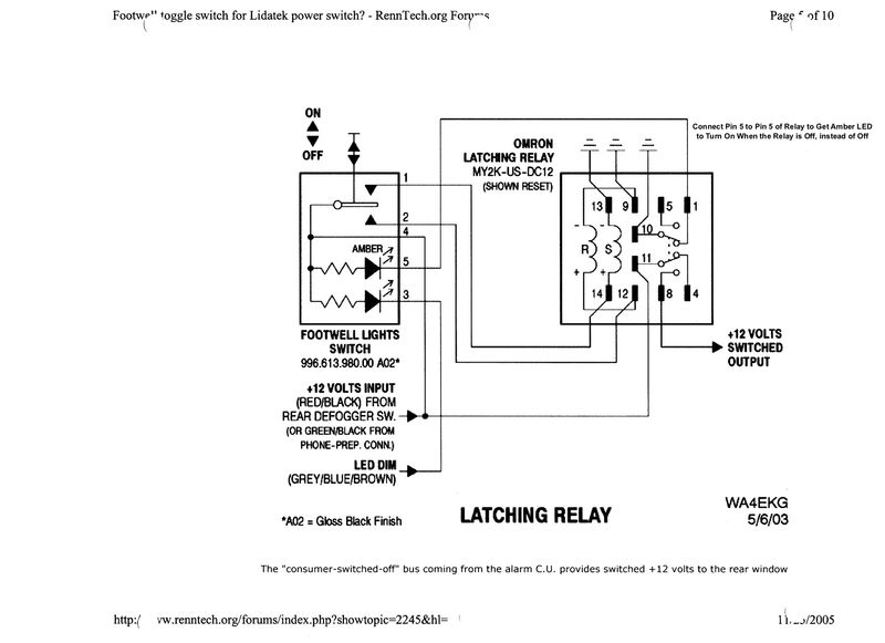
I am still trying to figure out how to make an OEM switch work. I found this diagram in the thread I mentioned detailing how to setup a latching relay. My question is will the entire thing will still work if I am using it to interrupt grounding a wire, not to connect a 12V input to a 12V output? Will the amber indicator light still work?
__________________
1999 Ocean Blue Metallic Boxster - blueboxster.com
|
|
|
|
|
05-23-2018, 12:41 PM
|
#5
|
|
Custom User Title Here
Join Date: Mar 2012
Location: Ft. Leonard Wood
Posts: 6,169
|
Instead of connecting pin #11 on the latching relay to 12V+, just ground it. That will make the output on pin #8 ground and everything else will work as shown.
|
|
|
|
|
05-23-2018, 07:59 PM
|
#6
|
|
There Is No Substitute.
Join Date: May 2007
Location: West Coast
Posts: 3,253
|
Particlewave, I can't thank you enough for the clarification and your other helpful posts, particularly the one about the different types of switches.
One last question, the symbol above relay pins 9, 10, 13 indicates those pins should be grounded, correct?
I am already working on a DIY for this. Figuring this out also inspired me to look at all of my previous electrical projects, and convinced me I need to redo some of my wiring from 10+ years ago had way too much electrical tape. I also might finally swap out my OBC footwell switch with the base from a Type A convertible top base to enable nighttime illumination.
__________________
1999 Ocean Blue Metallic Boxster - blueboxster.com
|
|
|
|
|
05-23-2018, 10:27 PM
|
#7
|
|
Custom User Title Here
Join Date: Mar 2012
Location: Ft. Leonard Wood
Posts: 6,169
|
No problem 
Yes, those are ground symbols.
|
|
|
|
|
12-01-2018, 11:26 PM
|
#8
|
|
Registered User
Join Date: Sep 2009
Location: toronto
Posts: 2,668
|
Where do plan on mounting this relay.......I have wondered if these can be mounted in the relay rack behind the fuse box somehow. There will one of these for every function and things could get really busy. For instance one might want:
-left rad fan switch
-right rad fan switch (or combine with above)
-engine bay cooling switch
-oil / trans cooler fan switch
-iPad charge power disconnect etc....
Is there one module commercially available to connect various accessory loads, and then have them controlled by the appropriate 986 momentary contact switch? This would make things easier for changes and or adding functions....You would just have to mount one oblong box
__________________
986 00S
|
|
|
|
|
12-02-2018, 06:02 AM
|
#9
|
|
There Is No Substitute.
Join Date: May 2007
Location: West Coast
Posts: 3,253
|
I actually just finished purchasing all of the parts when Sunset was doing 20% off everything last week. I already have the relay and plan to combine the left and right radiators to run on high only (since the low fans run with the AC, and the temp range where you want to trigger the fans manually means you are likely already running the AC).
My plan was to mount the relay behind the batwing where I plan to install the switch. It is a smaller relay than the standard ones in the car, so mounting it in the relay panel would require fabricating a custom mount, I also prefer to keep the wiring in the same area.
I will do a full right up when I finally get the parts then get around to doing the actual install, which probably won't be for a few more months. I may add an extra lead for connecting the engine bay fan to the same switch, but that requires running a wire from the rear trunk to the cabin.
__________________
1999 Ocean Blue Metallic Boxster - blueboxster.com
|
|
|
|
|
12-02-2018, 08:42 PM
|
#10
|
|
Registered User
Join Date: Sep 2009
Location: toronto
Posts: 2,668
|
Sounds good. Nice plan. Did you end up using the Omron relay in the post below?
If you are able to impart any advice for removing these 986 dash switches from mushy soft look plastic panels it would be much appreciated.
I am bit of a Neanderthal when it comes to fine trim and electrical work.....so I am fearful of snapping something.
These switches are really in there!
__________________
986 00S
Last edited by jaykay; 12-02-2018 at 08:59 PM.
|
|
|
|
|
12-03-2018, 01:06 PM
|
#11
|
|
There Is No Substitute.
Join Date: May 2007
Location: West Coast
Posts: 3,253
|
I bought the same Omron latching relay shown in the diagram, it was around $20. Luckily, the fan switch will be installed in a 996 two button batwing along with a new garage door opener switch. I don't remember how I did my dash switches, I think I may have used a used a butter knife and lot of swear words. Good luck!
__________________
1999 Ocean Blue Metallic Boxster - blueboxster.com
|
|
|
|
|
09-06-2019, 08:16 PM
|
#12
|
|
There Is No Substitute.
Join Date: May 2007
Location: West Coast
Posts: 3,253
|
Particlewave, I need your wisdom! 
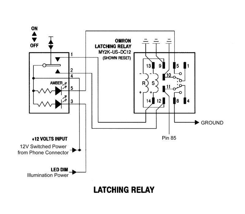
This is the wiring diagram I used when I wired this modification. I just hooked up the illumination wiring and the fan switch is always illuminated (backlit). When I turn the headlights on the switch backlight changes to my set backlight brightness (set by the knob on the instrument cluster), however the backlight is operating inversely to everything else. If I raise the brightness the switch gets dimmer, if I decrease the brightness the switch gets brighter.
If I swap out the 12V from the phone connector (Switch Pin 4) with the Illumination+ and put Illumination- on Pin 3, the backlight works properly but since the latching relay requires 12V the switch only works with the headlights on.
When I try the Illumination- on Pin 3 instead of the Illumination+, the switch is still always illuminated, but I lose any brightness adjustment.
I have tried every configuration I can think of and am completely stumped as to why the switch is acting like this. I believe it "should" work, but it doesn't. I would greatly appreciate any insight, because I have been racking my brain for the last several hours.
The only solution I have come up with that actually works (switch only illuminated when headlights are on and brightness adjusts properly) is to insert a 4 Pin Relay, like this, but I don't really know why this is any better. Thank you!

__________________
1999 Ocean Blue Metallic Boxster - blueboxster.com
Last edited by rick3000; 09-06-2019 at 08:18 PM.
|
|
|
|
|
09-06-2019, 10:50 PM
|
#13
|
|
Custom User Title Here
Join Date: Mar 2012
Location: Ft. Leonard Wood
Posts: 6,169
|
Your problem is pin 3.
The LED on pin 3 is the illumination LED.
The LED on pin 5 is the indicator that is active with the latching relay.
It sounds to me like your illumination/dim “power” on pin 3 is + instead of ground (must be ground for the LED to work). Where did you tap for this source?
Does the pin 5 indicator LED illuminate when the latching relay is activated?
Last edited by particlewave; 09-06-2019 at 10:52 PM.
|
|
|
|
|
09-06-2019, 11:07 PM
|
#14
|
|
Custom User Title Here
Join Date: Mar 2012
Location: Ft. Leonard Wood
Posts: 6,169
|
I just noticed in your post that you mentioned an “illumination +”.
The positive is constant (from pin 4/phone connector) and the ground is switched/dimmed in the backlight circuit. Just use a good switched 12V+ on pin 4 (phone connector) and dim ground on 3.
BTW, a good source for dim ground is the Gray/Blue/Brown wire on pin 3 of the original dash defrost switch.
Last edited by particlewave; 09-06-2019 at 11:48 PM.
|
|
|
|
|
09-07-2019, 06:26 AM
|
#15
|
|
There Is No Substitute.
Join Date: May 2007
Location: West Coast
Posts: 3,253
|
Thank you for the quick reply!
Your post got me thinking that the defroster switch I am using might be bad because it should work with the dim ground on Pin 3. That is what has been driving me crazy, it should work!
I decided to pull my left center console buttons out and test the wiring on a different defroster switch. While I was there, I decided to try bypassing all of the illumination wiring I was running from the cigarette lighter down to the batwing just to see what would happen, same thing, switch is always on. Then I decided to try using the illumination going to Pin 3 of the defroster switch like you suggested, and it works! Thank you!
After looking in the Bentley Manual, there is something different about the wiring. Unlike everything else that is wired to DIM LED TERM.58d, the defroster switch is wired to DIM LED TERM.31d. Now that I have resolved this, I will tap into the defroster switch and run another wire to power the illumination for this switch.
Also, the indicator light works perfectly with the latching relay!
__________________
1999 Ocean Blue Metallic Boxster - blueboxster.com
|
|
|
|
|
09-07-2019, 10:02 AM
|
#16
|
|
Custom User Title Here
Join Date: Mar 2012
Location: Ft. Leonard Wood
Posts: 6,169
|
Glad you got it sorted out, Rick!
|
|
|
|
 Posting Rules
|
You may not post new threads
You may not post replies
You may not post attachments
You may not edit your posts
HTML code is On
|
|
|
All times are GMT -8. The time now is 10:41 AM.
| |


 Porscha
 Linear Mode


