 06-11-2016, 07:07 AM
|
#101
|
|
Registered User
Join Date: May 2015
Location: Sydney, Australia
Posts: 335
|
Hey guys, I need some help with this, I've built this twice now and I just can't get it to work. The code and electronics in theory are working fine, I've breadboarded it all up with a couple of led's to simulate the top motor and can turn them on and off with the buttons, but when I get it in the car... nothing.
If I put a multimeter between the regular harness and switch, when I press the button I see 12v @ ~70ma when the top's moving, which drops to ~10ma when the top stops. But when I do it between the arduino and the harness I see 12v @ ~30ma. I'm guessing this is the reason it doesn't work, not pushing enough power through to activate the motor, but I don't know why?
I've built it twice now, thinking I must have screwed up the first one, but the second has exactly the same result :/
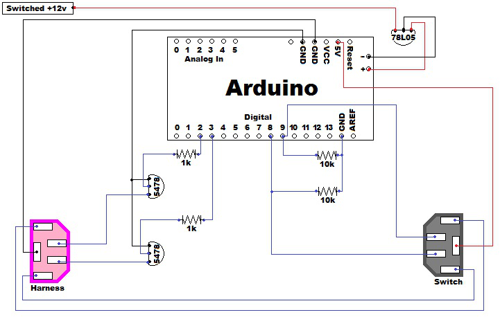
The only difference I can see in my build is I'm using a nano, which has no +/- and only 2 GND. So the VR goes to the VIN and one GND, leaving one free GND which I connect to from the harness, and which both switches (via the 10k resistors) and both transistors (via the collector pins) are wired to. Is this wrong?
I'm just a simple software guy, so all these wires and pins confuse me. Any help appreciated!
Thanks!
Last edited by oldskool73; 06-11-2016 at 07:10 AM.
|

|

|
|
06-28-2016, 09:21 AM
|
#102
|
|
Registered User
Join Date: Aug 2014
Location: Fort Collins, Colorado
Posts: 345
|
Quote:
Originally Posted by Polaris

Parts List:
-5 male automotive crimp-on connectors
-5 female automotive crimp-on connectors
-1 splice connector
|
I ordered the Arduino Nano board for $5.88 shipped.  ATMEGA328 Compatible Nano V3 Improved Version Board with USB Cable for Arduino | eBay ATMEGA328 Compatible Nano V3 Improved Version Board with USB Cable for Arduino | eBay
I have put all of the components in a cart on Mouser and am now trying to get the connectors.
Does anyone know the specifics of these automotive crimp-on connectors so that they fit between the harness and the switch?
Thanks, John
__________________
2001 Boxster S - Midnight Blue Metalic
|
|
|
|
|
06-28-2016, 10:43 AM
|
#103
|
|
On the slippery slope
Join Date: Mar 2014
Location: Austin and Palm Springs
Posts: 3,805
|
__________________
2004 Boxster S 6 speed - DRL relay hack, Polaris AutoTop DIY
2004 996 Targa Tip
Instructor - San Diego region
2014 Porsche Performance Driving School
2020 BMW X3, 2013 Ram 1500, 2016 Cmax, 2004 F-150 "Big Red"
|

|
|
|
06-28-2016, 11:57 AM
|
#104
|
|
Registered User
Join Date: Aug 2014
Location: Fort Collins, Colorado
Posts: 345
|
Quote:
Originally Posted by JayG
|
Thanks! I ordered the components and will go to HD to get the connectors! Can't wait to get this project rolling!
John
__________________
2001 Boxster S - Midnight Blue Metalic
|
|
|
|
|
06-28-2016, 01:25 PM
|
#105
|
|
On the slippery slope
Join Date: Mar 2014
Location: Austin and Palm Springs
Posts: 3,805
|
Quote:
Originally Posted by jpc763
Thanks! I ordered the components and will go to HD to get the connectors! Can't wait to get this project rolling!
John
|
Make sure you get the correct ones for the wire gauge you are using.
IIRC, I used red ones. The package tells you what gauge wire will fit
__________________
2004 Boxster S 6 speed - DRL relay hack, Polaris AutoTop DIY
2004 996 Targa Tip
Instructor - San Diego region
2014 Porsche Performance Driving School
2020 BMW X3, 2013 Ram 1500, 2016 Cmax, 2004 F-150 "Big Red"
|
|
|
|
|
06-28-2016, 02:00 PM
|
#106
|
|
Registered User
Join Date: Aug 2014
Location: Fort Collins, Colorado
Posts: 345
|
Quote:
Originally Posted by JayG
Make sure you get the correct ones for the wire gauge you are using.
IIRC, I used red ones. The package tells you what gauge wire will fit
|
What gauge wire should I be using?
John
__________________
2001 Boxster S - Midnight Blue Metalic
|
|
|
|
|
06-28-2016, 02:27 PM
|
#107
|
|
On the slippery slope
Join Date: Mar 2014
Location: Austin and Palm Springs
Posts: 3,805
|
Quote:
Originally Posted by jpc763
What gauge wire should I be using?
John
|
I used 16 gauge, so I guess I used blue terminals
__________________
2004 Boxster S 6 speed - DRL relay hack, Polaris AutoTop DIY
2004 996 Targa Tip
Instructor - San Diego region
2014 Porsche Performance Driving School
2020 BMW X3, 2013 Ram 1500, 2016 Cmax, 2004 F-150 "Big Red"
|
|
|
|
|
07-01-2016, 01:45 AM
|
#108
|
|
Registered User
Join Date: Nov 2015
Location: South Wales, UK
Posts: 852
|
Quote:
Originally Posted by oldskool73
Hey guys, I need some help with this, I've built this twice now and I just can't get it to work. The code and electronics in theory are working fine, I've breadboarded it all up with a couple of led's to simulate the top motor and can turn them on and off with the buttons, but when I get it in the car... nothing.
If I put a multimeter between the regular harness and switch, when I press the button I see 12v @ ~70ma when the top's moving, which drops to ~10ma when the top stops. But when I do it between the arduino and the harness I see 12v @ ~30ma. I'm guessing this is the reason it doesn't work, not pushing enough power through to activate the motor, but I don't know why?
I've built it twice now, thinking I must have screwed up the first one, but the second has exactly the same result :/
The only difference I can see in my build is I'm using a nano, which has no +/- and only 2 GND. So the VR goes to the VIN and one GND, leaving one free GND which I connect to from the harness, and which both switches (via the 10k resistors) and both transistors (via the collector pins) are wired to. Is this wrong?
I'm just a simple software guy, so all these wires and pins confuse me. Any help appreciated!
Thanks!
|
Personally I'd buy a One just to be absolutely sure that everything is the same as the build. I did and it works as I didn't want to get anything wrong. Originally I bought a cheap ebay rip-off and it didn't work, then I bit the bullet and bought a proper Arduino One for £20 and it worked first time 
__________________
Porsche Boxster S Type 986
Bi-xenon Headlight Upgrade | 987 S 18" Anthracite Alloys | Android Head Unit | 5000k 55w HID's | 5000k Cree DRL's | 5000k Cree number plate lights | Cree LED Indicators | One-touch roof operation | Bypass exhaust pipes | Parking sensors | Ambient footwell lighting
|
|
|
|
|
07-07-2016, 10:52 PM
|
#109
|
|
Registered User
Join Date: May 2015
Location: Sydney, Australia
Posts: 335
|
Thanks @geraintthomas, gonna hang on and see if @jpc763 has any luck with his nano first, hopefully he reports back...
|
|
|
|
|
07-08-2016, 08:57 AM
|
#110
|
|
Registered User
Join Date: Aug 2014
Location: Fort Collins, Colorado
Posts: 345
|
I will post when I complete the project.
__________________
2001 Boxster S - Midnight Blue Metalic
|
|
|
|
|
07-16-2016, 07:13 PM
|
#111
|
|
Registered User
Join Date: Aug 2014
Location: Fort Collins, Colorado
Posts: 345
|
Quote:
Originally Posted by Polaris
Schematic:
 |
Quote:
Originally Posted by JayG
OK, finally got a chance to take a few pics

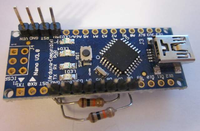 |
OK. I am starting the project and have a few questions. I was a code guy back in the day but have done some electronics. I am using a breadboard to wire it up before I solder everything together.
Here is a picture of my nano. I am trying to figure out how to match the pinouts from Polaris's Arduino. Mine is more like JayG.
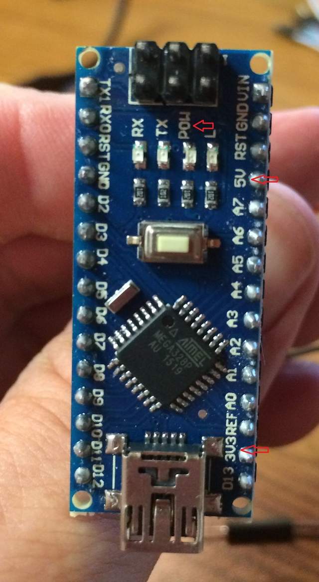
I assume that the "-" on the end is simply ground and will solder to the other ground wires. The "+" is a question as I have both 5v, 3.3v and pow pins. So, which do I connect the power regulator to?
__________________
2001 Boxster S - Midnight Blue Metalic
|
|
|
|
|
07-16-2016, 09:19 PM
|
#112
|
|
On the slippery slope
Join Date: Mar 2014
Location: Austin and Palm Springs
Posts: 3,805
|
The regulator connects to +5v
__________________
2004 Boxster S 6 speed - DRL relay hack, Polaris AutoTop DIY
2004 996 Targa Tip
Instructor - San Diego region
2014 Porsche Performance Driving School
2020 BMW X3, 2013 Ram 1500, 2016 Cmax, 2004 F-150 "Big Red"
|
|
|
|
|
09-14-2016, 08:14 AM
|
#113
|
|
Registered User
Join Date: Nov 2012
Location: Quebec, Canada
Posts: 29
|
Does anyone have the shcematic for the arduino nano? It is hard to find out wich is the pin out number on the arduino nano it is very different then the schematic that polaris did.
Thanks guys!
__________________
 André :
|
|
|
|
|
09-16-2016, 08:53 AM
|
#114
|
|
Registered User
Join Date: Apr 2013
Location: Springfield, Oregon
Posts: 62
|
Everything is on the digital pins, and it should correspond to the same pin-out numbers even if they are in a different order.
Alternatively, all the pinouts are set up through constants, so you can change the pinouts the code uses by changing the constants at the top of the code before compiling and uploading to your arduino.
I have made this successfully with both the arduino one (my original version) and eBay Chinese nanos without issue, so it should be possible.
|
|
|
|
|
03-02-2017, 12:38 PM
|
#115
|
|
Registered User
Join Date: Dec 2009
Location: USA
Posts: 262
|
Hello Polaris,
Coming late to the AutoTop party.
The link to the arduino code is broken in your original post.
Where can I find the code?
Thank you in advance.
|
|
|
|
|
03-03-2017, 06:07 PM
|
#117
|
|
Registered User
Join Date: Dec 2009
Location: USA
Posts: 262
|
Quote:
Originally Posted by oldskool73
|
Thank you oldskool73!!
P. S. Do you also know where I can get the circuit diagram? Thank you in advance.
|
|
|
|
|
03-13-2017, 07:48 AM
|
#118
|
|
Auto Locksmith
Join Date: Mar 2017
Location: UK
Posts: 2
|
Hi Guys.
If anyone has the schematic I would be most grateful.
Thanks
|
|
|
|
|
03-13-2017, 04:20 PM
|
#119
|
|
On the slippery slope
Join Date: Mar 2014
Location: Austin and Palm Springs
Posts: 3,805
|
Here is the Schematic
__________________
2004 Boxster S 6 speed - DRL relay hack, Polaris AutoTop DIY
2004 996 Targa Tip
Instructor - San Diego region
2014 Porsche Performance Driving School
2020 BMW X3, 2013 Ram 1500, 2016 Cmax, 2004 F-150 "Big Red"
|
|
|
|
|
03-13-2017, 04:22 PM
|
#120
|
|
Auto Locksmith
Join Date: Mar 2017
Location: UK
Posts: 2
|
Thanks, I will build it tomorrow.
|
|
|
|
 Posting Rules
|
You may not post new threads
You may not post replies
You may not post attachments
You may not edit your posts
HTML code is On
|
|
|
All times are GMT -8. The time now is 05:32 AM.
| |


 2004 Porsche Boxster S
 2004 Porsche 996 Targa
 Boxster
 Garage Queen
 Linear Mode


