I've been using my home-brew Arduino based AutoTop for the last year without any problems or magic smoke, so I think it's time to post a DIY guide for everybody:
There are a few options for automatic top openers/closers, but they range from $100 to over $200. I like to tinker, so I had an extra Arduino knock-off and parts laying around, so I thought I'd give making my own a go. The parts total should come out to $15 or so if you purchase an Arduino Nano clone on eBay for around $5 (inc. shipping) and the rest of the parts from somewhere like Mouser.com. I used an extra standard sized Arduino Uno clone I had laying around.
The functionality of this matches the way the windows work: Quick press open to auto-open, quick press close to auto close, long press open to manually open for the length of the press (for engine access), and long press close to manually close for the length of the press. Also, for emergency purposes, a quick press of either open or close while the top is auto opening or closing will cancel the auto open or close process.
Parts List:
-Two BC547B Transistors
click here
-One 78L05 Voltage Regulator
click here
-Two 10K resistors (.5 watt should do)
-Two 1K resistors (.5 watt should do as well) (I think that was the value I used, I'll have to double check)
-5 male automotive crimp-on connectors
-5 female automotive crimp-on connectors
-1 splice connector
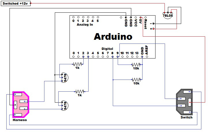
Schematic:
Arduino Code:
Click Here
Notes:
You'll need to wire up the Arduino as noted in the Schematic. Each connection to the harness and the switch terminate in male crimp-on connectors (for the harness side) and female crimp-on connectors (for the switch side). Three wires from the harness side and three wires from the switch side connect to the Arduino. The remaining two wires that go from the harness to the switch are just jumpers to allow the night time illumination to continue to work.
I labeled the "Open" and "Close" connectors on the harness and switch sides so they are easy to differentiate if I need to disconnect it at any time.
I ran the power lead to the switched power on the car stereo harness. I would suspect that it would probably be OK to have the Arduino powered all the time from the constant +12v on the harness, but I wanted to be sure I didn't drain the battery when the car was off, and I have an aftermarket stereo, so my power lead is actually soldered into my stereo's Porsche to Pioneer harness adapter.
I covered all exposed wires in shrink tubing, including the transistor leads. I also sheathed the entire Arduino in a thick plastic bag.
The code's open or close length is configurable by constant variables. You can edit the time used based on how long your top actually takes to open or close. I add a couple seconds to both open and close times so the top is sure to fully open or close.
I also did the "bend pin 18" trick on the top relay so I can activate the top while in motion with the parking brake on one click.


 Threaded Mode


