Quote:
Originally Posted by Polaris

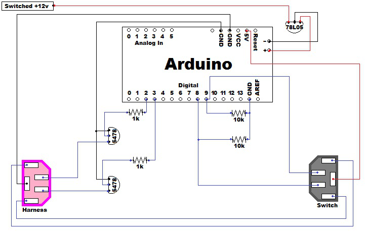
Schematic:
 |
Quote:
Originally Posted by JayG
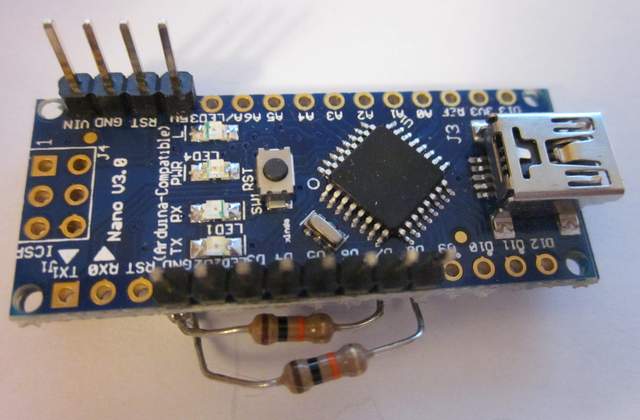
OK, finally got a chance to take a few pics

 |
OK. I am starting the project and have a few questions. I was a code guy back in the day but have done some electronics. I am using a breadboard to wire it up before I solder everything together.
Here is a picture of my nano. I am trying to figure out how to match the pinouts from Polaris's Arduino. Mine is more like JayG.
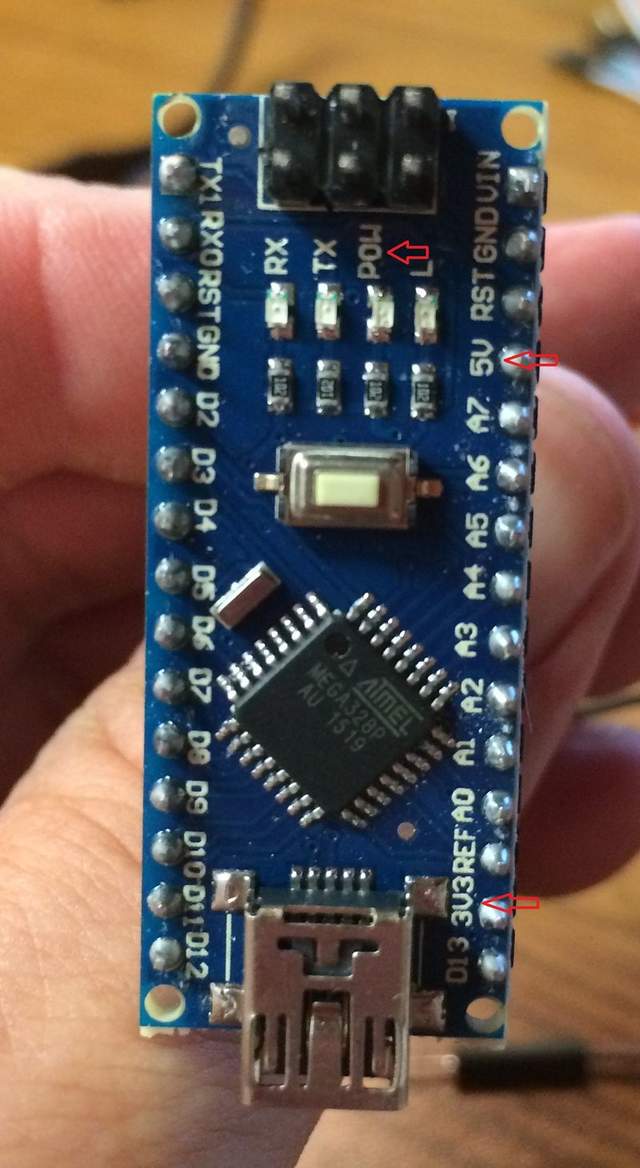
I assume that the "-" on the end is simply ground and will solder to the other ground wires. The "+" is a question as I have both 5v, 3.3v and pow pins. So, which do I connect the power regulator to?