Go Back   986 Forum - The Community for Porsche Boxster & Cayman Owners > Porsche Boxster & Cayman Forums > Performance and Technical Chat

Post Reply
 
LinkBack Thread Tools Display Modes
Old 11-05-2014, 11:34 AM   #1
Registered User
 
hemonu's Avatar
 
Join Date: Oct 2012
Location: Germany
Posts: 43
Garage
Quote:
Originally Posted by Madmax08154711 View Post
This is what I found, but I still need the pinout for Bosch cabel 1 684 462 386 or the Porsche cabel 000 721 958 85
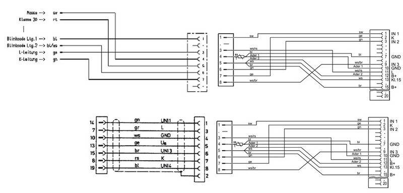
I got a PST-2 with the upper cables and an ODB2 breakout box. No description, so similar problem as you. I found another thread on rennlist.org and have the wiring diagramm for 2000 and 2001 model.

Lower part of your diagramm is the old round 19 pin service connector. I can map that connector to a 16 pin ODB2 as follows

14: TN/ rev counter is pin 9 on odb2
7: L line is pin 15 on odb2
10: GND is pin 4 and 5 on odb2. Has to be connected to both
13: switched +12V is pin 1 on odb2. You can use pin 16 alternatively
15: not used
19: knocking pulse is pin 11 on odb2. Not connected in 2001 model

8: thats the k line, which is the main communication line for the tester. If you connect it to pin 7 on odb2 you can communicate with dme and immobilizer. If you connect to pin 3 you can communicate to all other ECUs. According to the rennlist thread you have to connect to both. Thats makes sense and shouldn't be a problem, but I still have to test!

Good luck

Update: I just tested it. With k line connected to both pin 7 and pin 3 of odb2 i could activate my cruise control including the light in the instrument cluster. Seems to be correct :-)

Last edited by hemonu; 11-06-2014 at 11:58 PM. Reason: new information
hemonu is offline   Reply With Quote
Old 11-07-2014, 11:30 AM   #2
Registered User
 
Join Date: Oct 2014
Posts: 9
In addtition i found the following.


1999 Porsche Boxster OBDii connector pinout
Pin # OBD-II Purpose Porsche Specific Wire Color Notes
1 - power black/red max 5 Amps
2 - - -
3 - K line #2 orange/blue
4 chassis ground - -
5 sensor 0 volts - brown/blue do not use as a ground
6 - - -
7 ISO 9141-2 K line - orange/black
8 - - -
9 - TN signal violet/green tach wire, 12v square wave
10 - - -
11 - - blue/black
12 - sensor voltage red/yellow/black 5v sensor power
13 - - -
14 - - -
15 ISO 9141-2 L line - red/yellow
16 unswitched power - red/black max 5 Amps

So the question is was about the OBD2 Pin 12 (sensor voltage)

Last edited by Madmax08154711; 11-07-2014 at 11:32 AM.
Madmax08154711 is offline   Reply With Quote
Old 11-08-2014, 11:26 AM   #3
Registered User
 
hemonu's Avatar
 
Join Date: Oct 2012
Location: Germany
Posts: 43
Garage
Quote:
Originally Posted by Madmax08154711 View Post
In addtition i found the following.


1999 Porsche Boxster OBDii connector pinout
Pin # OBD-II Purpose Porsche Specific Wire Color Notes
1 - power black/red max 5 Amps
2 - - -
3 - K line #2 orange/blue
4 chassis ground - -
5 sensor 0 volts - brown/blue do not use as a ground
6 - - -
7 ISO 9141-2 K line - orange/black
8 - - -
9 - TN signal violet/green tach wire, 12v square wave
10 - - -
11 - - blue/black
12 - sensor voltage red/yellow/black 5v sensor power
13 - - -
14 - - -
15 ISO 9141-2 L line - red/yellow
16 unswitched power - red/black max 5 Amps

So the question is was about the OBD2 Pin 12 (sensor voltage)
pin 12 is not connected in the Boxster 00/01 wiring diagramms and I left it open.
hemonu is offline   Reply With Quote
Old 11-08-2014, 10:41 PM   #4
Registered User
 
Join Date: Oct 2014
Posts: 9
Quote:
Originally Posted by hemonu View Post
pin 12 is not connected in the Boxster 00/01 wiring diagramms and I left it open.
That is what I found

Madmax08154711 is offline   Reply With Quote
Old 11-09-2014, 12:46 AM   #5
Registered User
 
hemonu's Avatar
 
Join Date: Oct 2012
Location: Germany
Posts: 43
Garage
Quote:
Originally Posted by Madmax08154711 View Post
That is what I found

Are you sure, this is for a 986? Pin 6 and pin 14 looks like Can bus, which is used by the newer generation cars and Piwis software, but not pst2. Anyway there is only 8 pins in the amphenol connector of the pst2 and 5V is not in there.
hemonu is offline   Reply With Quote
Old 11-12-2014, 11:48 AM   #6
Registered User
 
Join Date: Oct 2014
Posts: 9
I build the following cable and did a test with a PST2 and an 2000 Boxster S and everything seems ok.

Madmax08154711 is offline   Reply With Quote
Old 01-05-2015, 08:09 AM   #7
Registered User
 
hemonu's Avatar
 
Join Date: Oct 2012
Location: Germany
Posts: 43
Garage
Quote:
Originally Posted by Madmax08154711 View Post
I build the following cable and did a test with a PST2 and an 2000 Boxster S and everything seems ok.

Be careful! With this cable you bridge Terminal 30 and Terminal 15 inside the AMP connector. If you plug the cable with ignition switched OFF you will energise Terminal 15, which may easily blow some fuse(s) or do other harm. You better do only one of the two terminals to AMP contact 5. It doesn't matter which one.
hemonu is offline   Reply With Quote
Post Reply

Tags
kts 500 , pinout , pst2


Posting Rules
You may not post new threads
You may not post replies
You may not post attachments
You may not edit your posts

BB code is On
Smilies are On
[IMG] code is On
HTML code is On
Trackbacks are On
Pingbacks are On
Refbacks are On


All times are GMT -8. The time now is 02:36 PM.


Powered by vBulletin® Version 3.8.7
Copyright ©2000 - 2025, vBulletin Solutions, Inc.
Content Relevant URLs by vBSEO 3.6.0
Copyright 2025 Pelican Parts, LLC - Posts may be archived for display on the Pelican Parts Website -    DMCA Registered Agent Contact Page