 05-26-2012, 03:42 PM
|
#1
|
|
Registered User
Join Date: Jul 2011
Location: Richmond, VA (The Fan)
Posts: 978
|
IMS Install help! IMS bearing not centered
So far the IMS/clutch job has gone smoothly, and the bearing seems to be in great shape but I have no idea how I'm going to remove the thing! Its not centered in the hole so the the puller is not going to work. Any ideas, I'm not sure how the cover worked since it would have to be centered for it to be bolted up. Any ideas?

__________________
1997 Boxster 4.2L Audi V8 Bi-Turbo
2003 911 C2
NASA HPDE Instructor
|

|

|
|
05-26-2012, 03:53 PM
|
#2
|
|
Registered User
Join Date: Jul 2011
Location: Richmond, VA (The Fan)
Posts: 978
|
****************! I ddin't take the cam tensioners out. Hopefully I didn't bend anything. Does anyone know what size those wrench those tensioners need?
__________________
1997 Boxster 4.2L Audi V8 Bi-Turbo
2003 911 C2
NASA HPDE Instructor
|
|
|
|
|
05-26-2012, 04:19 PM
|
#3
|
|
Registered User
Join Date: Jul 2010
Location: California
Posts: 1,859
|
You needed to remove the chain tensioners... 32mm.
__________________
Jäger
300K Mile Club
|
|
|
|
|
05-26-2012, 04:25 PM
|
#4
|
|
Registered User
Join Date: Jul 2011
Location: Richmond, VA (The Fan)
Posts: 978
|
well its closer but still not dead centered. The puller might center the bearing but I'm not sure if thats a good idea. Its very close but the inside of the puller is still contacting a small part of the bearing. What do guys think I should do? Go ahead and try and pull it?
__________________
1997 Boxster 4.2L Audi V8 Bi-Turbo
2003 911 C2
NASA HPDE Instructor
|
|
|
|
|
05-26-2012, 04:28 PM
|
#5
|
|
Registered User
Join Date: Jul 2010
Location: California
Posts: 1,859
|
Did you put your motor at TDC and lock the crank and then the cams on one side?

__________________
Jäger
300K Mile Club
|
|
|
|
|
05-26-2012, 04:36 PM
|
#6
|
|
Registered User
Join Date: Jul 2011
Location: Richmond, VA (The Fan)
Posts: 978
|
No, the pelican article I'm using didn't mention it. I do have the lock down bolts around the IMS bearing in place now and have marked the cam shafts. Unfortunately the engine is not at TDC and I'm hesitant to turn it over with out the IMS support plate in place.
__________________
1997 Boxster 4.2L Audi V8 Bi-Turbo
2003 911 C2
NASA HPDE Instructor
|
|
|
|
|
05-26-2012, 05:00 PM
|
#7
|
|
Registered User
Join Date: Jul 2010
Location: California
Posts: 1,859
|
Did you remove the chain tensioners?
__________________
Jäger
300K Mile Club
|
|
|
|
|
05-26-2012, 05:09 PM
|
#8
|
|
Registered User
Join Date: Jul 2011
Location: Richmond, VA (The Fan)
Posts: 978
|
I removed the two at the back of the engine. Apparently there is a third tensioner that pelican doesn't mention? So far my internet searches haven't told me where this thing is. I did try and pull the bearing with no luck, I put quite a bit of force on it but I didn't want to go to far. How much does it take?
__________________
1997 Boxster 4.2L Audi V8 Bi-Turbo
2003 911 C2
NASA HPDE Instructor
|
|
|
|
|
05-26-2012, 05:15 PM
|
#9
|
|
Registered User
Join Date: Jul 2010
Location: California
Posts: 1,859
|
No need to remove the tensioner that is in the front of the motor. I see you have two set screws holding the IMS sprocket... Do you have a third set screw? If so, install it and try to center the IMS by loosening the right side a little and tightening the left side (as viewed in your picture). After you have it centered tighten them down but don't over torque them.
__________________
Jäger
300K Mile Club
|
|
|
|
|
05-26-2012, 05:22 PM
|
#10
|
|
Registered User
Join Date: Jul 2010
Location: California
Posts: 1,859
|
Is your new bearing in the freezer? It needs to be in the freezer for a couple of hours.
__________________
Jäger
300K Mile Club
|
|
|
|
|
05-26-2012, 06:04 PM
|
#11
|
|
Registered User
Join Date: Jul 2010
Location: California
Posts: 1,859
|
Quote:
Originally Posted by truegearhead

I removed the two at the back of the engine. Apparently there is a third tensioner that pelican doesn't mention? So far my internet searches haven't told me where this thing is. I did try and pull the bearing with no luck, I put quite a bit of force on it but I didn't want to go to far. How much does it take?
|
It will take a little force to pull the bearing, this is a machine pressed fit you are pulling out. Make sure the bearing is centered in your puller.
__________________
Jäger
300K Mile Club
|
|
|
|
|
05-29-2012, 08:58 AM
|
#12
|
|
Registered User
Join Date: Apr 2009
Location: SF Bay Area
Posts: 247
|
This is why JFP specifically told you:
Take your time, read and follow the LN directions (I am not a fan of using setscrews to hold the shaft).
I wouldnt remove the bearing without removing the tensioners. Thats how I did mine and didnt have this problem. Also, if you have that much oil leaking past the bearing, it may not be in such good shape. When you get it out, I bet theres some play in it.
__________________
2003 Cayenne Turbo
|
|
|
|
|
05-29-2012, 10:13 AM
|
#13
|
|
Registered User
Join Date: Feb 2005
Location: It's a kind of magic.....
Posts: 6,693
|
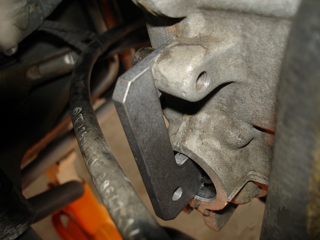
There is no way to sugar coat this, you are probably in trouble. The engine should have been rotated to TDC and locked in place with the pin pictured above. You should have then pulled the cam plugs on one head and locked the cam with the fixture pictured above. Then, and only then, you should have pulled three tensioners, which would have allowed the shaft to remain centered in the case opening when the rear IMS cover was removed. At this point, the IMS bearing would come right out, and the new one would go back in without issues.
I do not like using the set screws on the IMS rear gear because it is a press fit to the shaft and can easily be moved by pushing on it with the screws; and if it moves, there is no way to move it back to where it needs to be. At that point, the engine has to come out and come apart. Using only two setscrews could easily cause this problem.
At this juncture, I really do not know what advice to offer you, other than to suggest you probably need to flatbed the car to a shop that is better equipped to handle something like this.
For future “searchers” coming across this post, here is the way you are supposed to do this, written by the two guys that originally figured how to successfully do this. Just remember, shortcuts are the quickest pathways to a disaster:
LN Engineering Retrofit Kit Instructions - Rev 7 Jul 10.
1. PROFESSIONAL INSTALLATION RECOMMENDED and required for limited warranty. See
enclosed warranty form. WE DO NOT PROVIDE SUPPORT FOR INSTALLATIONS!
2. Dual row retrofit kit for dual row only IMS's & single row kit for single row only!
3. If engine is running, use PST2, PIWIS, or equivalent tester to read live DME values for rough running
threshold and camshaft deviation.
4. Prior to starting this repair, drain oil, remove filter and oil pan and inspect for debris and clean. If any foreign
object debris is present from an IMS bearing that was in the process of failing or failed, we recommend installing a
magnetic drain plug and spin-on full flow oil filtration kit (both sold separately).
5. Put engine at TDC, and lock out the pulley so the engine cannot turn over.
6. Pull cam plugs and make note of position. It is recommended that the cams are locked out using factory cam
timing tool. If two sets of cam tools are available, it is possible to modify the tool to allow both sets of cams to be
locked, even with the engine in the car.
7. Then remove the three (3) chain tensioners. If worn or noisy, replace.
8. Remove hub flange.
9. If center stud/bearing support is broken, use Kukko 21-4 internal extractor to pull from inner race. If all
that remains is an outer race, a Kukko 21-6 internal extractor with a 22-2 counterstay can be used to pull from the
outer race. If the bearing has “welded” itself around the perimeter of the bearing housing bore or snap ring groove is
damaged in any way, do not proceed with the IMS retrofitting.
10. If it is a single row bearing, remove the snap ring. Otherwise, for dual row bearings, proceed as the retaining
wire-loc is internal and will collapse as you pull on it.
11. Thread hex bar adapter onto existing bearing support / center stud (already attached to bearing puller, sold
separately)
12. Adjust nut until sleeve of bearing puller is resting on the face of the intermediate shaft (around bearing
housing bore) and lubricate puller before extracting bearing. When bearing has been extracted, the bearing and puller
will come away from the engine as a single unit.
13. Clean out IMS tube to ensure no debris (if present) enters crankcase.
14. Remove nut and SPARE o-ring from new bearing support (already pressed into new bearing in center race)
and slide the aluminum bearing driver/installation tool over the stud, counter-bored side facing outside of engine.
Drop in 12 point nut and snug up to hold the bearing, bearing support/center stud, and bearing driver/installation tool
as a single unit.
15. Holding the installation tool, use a snap on dead blow (red, plasticized hammer) and gently tap new bearing
into place. Intermediate shaft will move backwards towards the pulley side of the engine until the other end of the
shaft is resting on the backside of the oil pump console, so don't hammer too hard. Bearing should go in easy. Install
spiro-loc on dual row or snap-ring on single row bearing.
16. You are now ready to install the new hub flange. Inspect seal for damage as well as bore in the block for any
imperfections that might cause the new seal or flange to leak. Take care not to damage o-ring located in new hub
flange, using an o-ring lubricant on seal to facilitate easy installation. Once new flange is started, use three (3) M6X25
bolts, tightening in a star pattern slowly to draw in the new hub flange in.
17. Once home, remove M6X25 bolts and replace with new micro-encapsulated bolts. Although optional, you can
use flange sealant on bottom of head of the bolt.
18. The center bearing support 12 point nut can be installed and torqued to the factory spec. Do not exceed 24
ft/lb if using the “goodandtight” method. Use flange sealant (Loctite 574 or Curil T) on bottom of head of the bolt and
use wicking (green) Loctite on the exposed threads of the center bearing support/stud and 12 point nut. If the small oring
is damaged or leaks, the use of flange and thread sealants should prevent a leak.
19. OPTIONAL Replace accessible case perimeter bolts with new factory micro-encapsulated bolts.
20. OPTIONAL Replace rear main seal with updated part number 997-101-212-01.
21. Although care has been taken to provide adequate clearance, care must be taken to ensure engine turns over
once flywheel/flex plate is installed (use new fasteners) and that there is no interference between the flange and
flywheel/flex plate. If there is interference, carefully grind the area of contact.
22. Engine timing should be verified after installation and re-timed if cam timing slips. If available, record DME
live value for rough running threshold and camshaft deviation. If deviation is more than 7.5 degrees, re-time cams.
__________________
Anything really new is invented only in ones youth. Later, one becomes more experienced, more famous and more stupid. - Albert Einstein
Last edited by JFP in PA; 05-29-2012 at 10:17 AM.
|

|
|
|
05-29-2012, 04:14 PM
|
#14
|
|
Engine Surgeon
Join Date: Aug 2008
Location: Cleveland GA USA
Posts: 2,425
|
Pulling any of the IMS related components with the engine in any other position than TDC and locked is absolutely going to lead to big time complications.. TDC is the ONLY location where the valve train is completely unloaded.
I have no idea why people do this over and over again both professional and DIY. Instructions don't help, because most don't read them and those who do generally don't absorb the information.
The VERY first thing that is done in this procedure is to locate TDC, the second thing is to lock the crank there...
I know- I developed the procedure from scratch and designed that puller~
__________________
Jake Raby/www.flat6innovations.com
IMS Solution/ Faultless Tool Inventor
US Patent 8,992,089 &
US Patent 9,416,697
Developer of The IMS Retrofit Procedure- M96/ M97 Specialist
|
|
|
|
|
05-29-2012, 05:41 PM
|
#15
|
|
Registered User
Join Date: Jul 2010
Location: California
Posts: 1,859
|
Quote:
Originally Posted by Jake Raby
Pulling any of the IMS related components with the engine in any other position than TDC and locked is absolutely going to lead to big time complications.. TDC is the ONLY location where the valve train is completely unloaded.
I have no idea why people do this over and over again both professional and DIY. Instructions don't help, because most don't read them and those who do generally don't absorb the information.
The VERY first thing that is done in this procedure is to locate TDC, the second thing is to lock the crank there...
I know- I developed the procedure from scratch and designed that puller~
|
I have over 20k miles on my self installed LNE bearing, your instructions work. Thank you for providing the installation information and making the bearings available for the "do-it-yourself" guys that enjoy working on their cars as much as they like driving them.
__________________
Jäger
300K Mile Club
|
|
|
|
|
05-30-2012, 03:36 AM
|
#16
|
|
Registered User
Join Date: Jul 2011
Location: Richmond, VA (The Fan)
Posts: 978
|
Jager thanks again for al your help. I took a few days off and dove back into the project last night. I modified the IMS removal tool by grinding an angle into it to help overcome the offset bearing, it worked great and the bearing came right out! The bearing really is in perfect shape, it looks and feels brand new and is a double row bearing. I still can't get the two header bolts I snapped out but I think I'm just going to reassemble everything and drag it to the shop to have them extracted.
__________________
1997 Boxster 4.2L Audi V8 Bi-Turbo
2003 911 C2
NASA HPDE Instructor
|
|
|
|
|
05-30-2012, 05:41 PM
|
#17
|
|
Registered User
Join Date: Jul 2010
Location: California
Posts: 1,859
|
Have you installed the new bearing?
__________________
Jäger
300K Mile Club
|
|
|
|
|
05-30-2012, 07:36 PM
|
#18
|
|
Registered User
Join Date: Jul 2011
Location: Richmond, VA (The Fan)
Posts: 978
|
Quote:
Originally Posted by Jager
Have you installed the new bearing?
|
I just got stuck. The bearing is in, I have a 97 so I have the dual row bearing. I installed the bearing, then the spacer and then the clip and everything seems to fit together nicely except that the spacing is off. See the attached pictures. I don't have room for the spacer under the nut. Is it possible that the write is written incorrectly and the spacer is designed to go on before the bearing?


__________________
1997 Boxster 4.2L Audi V8 Bi-Turbo
2003 911 C2
NASA HPDE Instructor
|
|
|
|
|
05-30-2012, 07:58 PM
|
#19
|
|
Registered User
Join Date: Jul 2011
Location: Richmond, VA (The Fan)
Posts: 978
|
Looks like there are two spacers in the kit, I only have one in mine. Anyone know how tall the shorter dual row spacer is?
EDIT: I found it! I'll install it tonight, stay tuned.
__________________
1997 Boxster 4.2L Audi V8 Bi-Turbo
2003 911 C2
NASA HPDE Instructor
Last edited by truegearhead; 05-31-2012 at 05:57 AM.
|
|
|
|
|
06-03-2012, 06:07 PM
|
#20
|
|
Registered User
Join Date: Jul 2011
Location: Richmond, VA (The Fan)
Posts: 978
|
I got a little side tracked and replaced my cv boots but finally started the car back up and everything seems to be in order. 2 exhaust manifold bolts are still busted so it's not all back together yet but at least I know she runs!
__________________
1997 Boxster 4.2L Audi V8 Bi-Turbo
2003 911 C2
NASA HPDE Instructor
|
|
|
|
 Posting Rules
|
You may not post new threads
You may not post replies
You may not post attachments
You may not edit your posts
HTML code is On
|
|
|
All times are GMT -8. The time now is 12:10 AM.
| |


 Jägermobile
 Jagermobiles
 Jager4Smobile
 Linear Mode


