Go Back   986 Forum - The Community for Porsche Boxster & Cayman Owners > Porsche Boxster & Cayman Forums > Performance and Technical Chat

Post Reply
 
LinkBack Thread Tools Display Modes
Old 08-03-2023, 01:30 PM   #1
Registered User
 
Join Date: Jan 2007
Location: BC
Posts: 1,328
Repairing door lock module Part 1 of 3

Time to pay it forward. Someone down the road might want to try fixing a door locking module. Due to site limitations to quantity of pics per post, I'll have to post three threads to show the whole story.

Model year 2001 Canadian car. Option 535 alarm. Porsche part # 3B1-837-016-P. Any directions given relate to the passenger side (right) door.

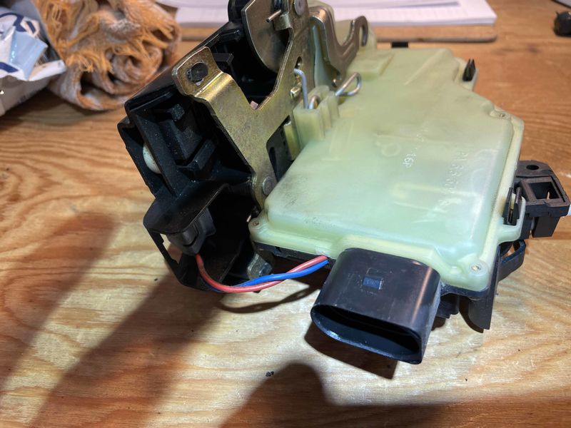
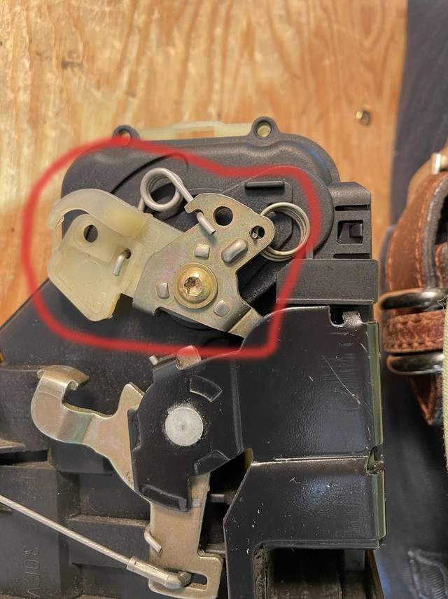
I had to take out the handle to have the door painted. The body guy lives a few km away so I thought I could just drive it there with the handle out but the door still latched, and then pull on the black latch connector on the lock module to open it when I got there.


So I tried pulling on the black connector at home first. Unfortunately I pulled too hard and was rewarded with a "snap". Hmm. Not good. After that I could not get the door to latch. Really not good.

When the car got home I tried a few things to make it work, all unsuccessful, so checking into the cost of a replacement module was next. The nearest dealer here north of the 49th had a list price of well over $700. Before taxes. Yikes. Apparently with the 535 alarm option the price was roughly double. Even with the employee discount it was still over $600 before taxes. The cheapest new on line was still around US$500 before taxes and shipping. LA Dismantlers had a used one from for a much better price, but by that time I'd decided I was going to try to fix mine. I thought it might be nothing more than an internal spring that had popped out of place.

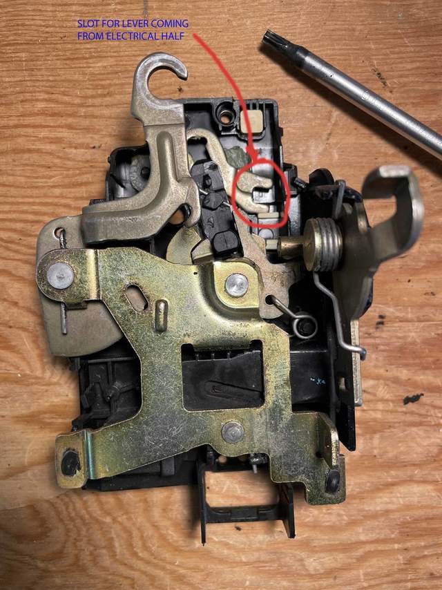
Follow online videos to get the door opened up. The handle doesn't have to be removed to re&re the lock module. Getting the lock module out is easy. First disconnect the black connector in the pic above from the screw on the handle, by sliding it towards the lock module to free up the screw, and then push up and down on it to pop out the threaded screw from the handle. Remove the 2 M8 triple square screws from the outside, and wiggle the whole thing out of the hole created by removing the brass plate (3 bolts, one of which is the bottom right airbag bolt). Hint: no need to remove the airbag for this job, and disconnecting it and re-connecting the battery without the airbag (as I did while checking things) will give you a nasty warning light. Fortunately I have a Durametric to cancel the fault.

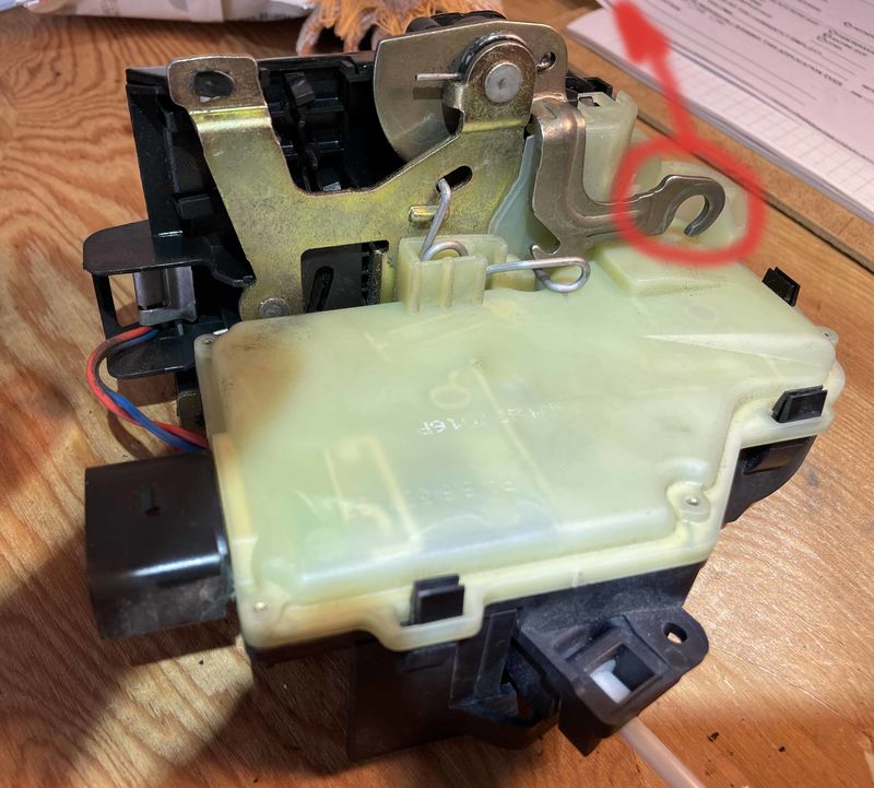
Once the module is out of the bowels of the door, remove the electrical connector.

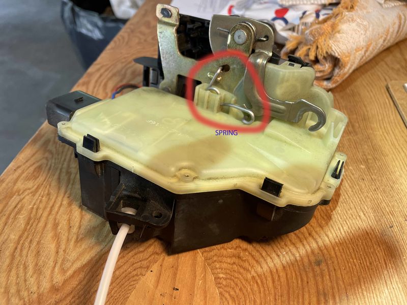
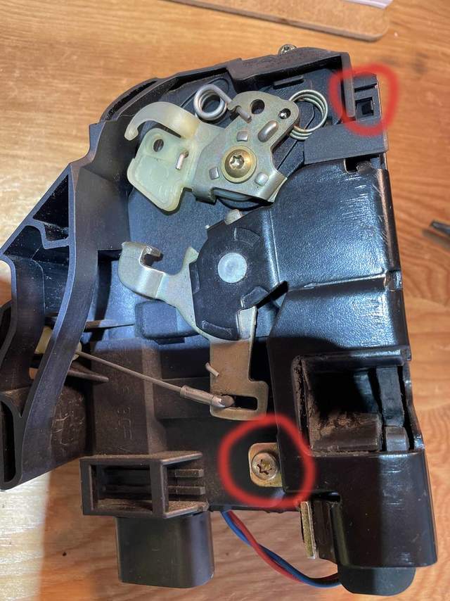
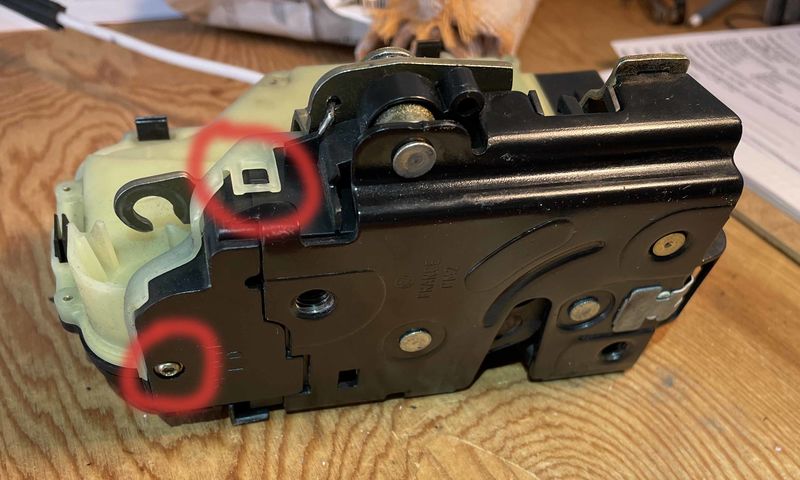
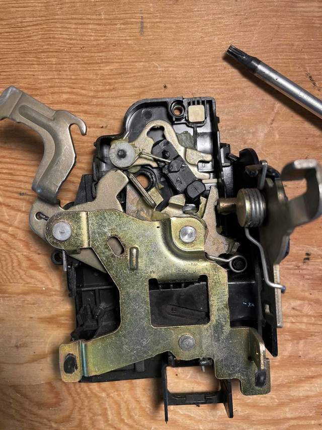
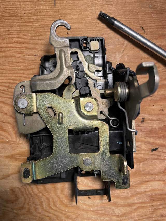
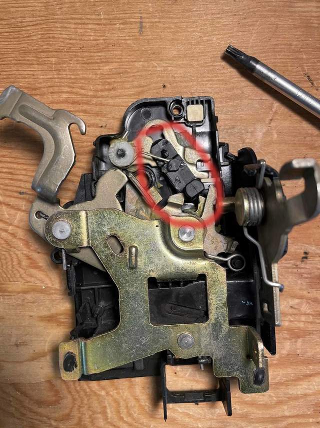
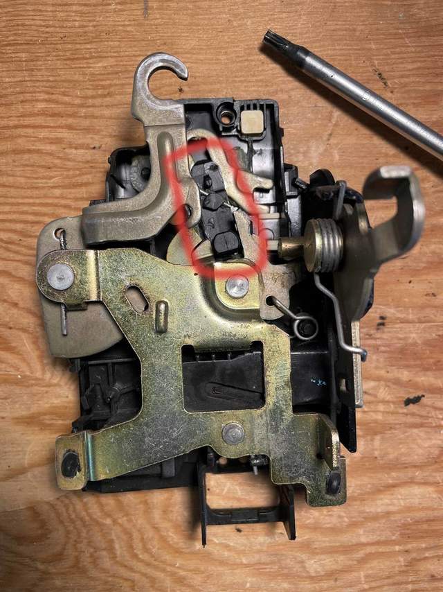
These pics show the module from various angles, including the inside latch release cable and its retainer.


To remove the inside latch release cable, first remove the black "retainer" by squeezing the 3 clips with pliers so they pop thru their retaining holes.


Then take a small flat screwdriver and pop out the cable. Turn the cable sideways to remove it from the narrow slot and set it aside.

Now you have the two-part module: mechanical and electrical. The mechanical half has the latch, and the electrical part has the amber-coloured plastic.


End of Part 1

__________________
2001 Boxster, 5 spd, Seal Grey
clickman is offline   Reply With Quote
Old 08-03-2023, 02:31 PM   #2
Registered User
 
Join Date: Jan 2023
Location: Ontario, Canada
Posts: 200
Adding part 2:
Quote:
Originally Posted by clickman View Post
Continued from Part 1.

To split the module in two, remove a spring and two screws and release two tab clips.


Unless you are going into the electrical half, don't remove this bracket and screw, like I did. The plastic piece under the bracket and screw is part of the inside of the electrical portion of the module, so it can become more complicated. More on that later.


With the two screws out and the tabs released, you can now wiggle the two halves of the module apart. It may help to move the outside latch release lever to the side.


First a pic of the guts of the mechanical half when I opened it. Then a pic of what it's supposed to look like. See the problem?


Here's the difference:


After playing with the outside latch actuating lever for a bit I discovered that my energetic pull during my initial experiment had popped the square black plastic knob out of its retainer. When I pushed it back into place, voila the latch started to work perfectly. That was it!?! At that point I wasn't overly impressed with the job the engineers had done; IMHO this shouldn't happen.

So the mechanical side was fixed!

Continued in Part 3.
redpepperracing is offline   Reply With Quote
Old 08-03-2023, 02:32 PM   #3
Registered User
 
Join Date: Jan 2023
Location: Ontario, Canada
Posts: 200
And part 3:
Quote:
Originally Posted by clickman View Post
Continued from Part 2.

So now re-assembly could begin. But first the bracket had to go back onto the electrical half, in the correct orientation to interface with the mechanical half. As I didn't know how it worked inside the electrical case, I had to take it apart. So I took out the little Torx screws and pulled it apart. Only I wasn't careful enough and the guts fell apart. Here's what it looked like.


The motor and its gear were loose, the circuit board was popped up from its mounting, and the little end journal cap on the worm gear was missing (took me a while to figure out what the little plastic cup laying in the bottom of the case was for).

The lock motor and its gear are on the left. They drive another ring gear on a worm gear, at centre of pic. The worm gear moves the white plastic lever on the right that goes thru the case as the female portion of the screw on the bracket I needed to orient. So the motor moves the worm gear, which moves the white lever, which moves the bracket on the outside of the case, which moves the lock selector in the mechanical half. (Note a limit switch mounted to the circuit board that is actuated by part of the white plastic bits moved by the worm gear.)

Once I got the journal cap back on and the motor and worm gear back in place, I had to make sure the white lever was in the right place for me to reattach the exterior bracket. On the interior side of the cover there is an oval that indicated the run of the white plastic on the worm gear, so I set the white plastic so it was in the center of the run, to give me an idea of how to mount the bracket once I had the electrical case closed up again. The bracket has to sit such that the arm going into the mechanical half sits in the slot there. (In retrospect, since there are only 3 tabs on the exterior of the white plastic, it would actually have been hard to get it wrong and have the lock lever on the bracket not be pointing to the right place in the mechanical half. As long as the bracket lever is pointing in the general direction of its counterpart slot in the mechanical half, it will allow you pick the right way to mount the bracket on the 3 tabs.)


Once the bracket arm was aimed in the right direction, the bracket could be screwed down in the correct orientation on the 3 tabs. Then the two halves of the module could be reunited, the two tabs snapped in place and the two screws installed. When putting together the two halves don't pull the lever arm that attaches to the door handle too far or you'll be taking the mechanical half apart yet again...

Next there is the spring to reinstall. Make sure this spring is in the right spot; apparently if you don't you could run into a number of problems. The spring snaps out of this spot with the first actuation of the door handle, so I think it's just there to ensure that when the door handle is connected to the module the lever arm is sitting in exactly the correct position.


Reattach the interior latch cable and snap on the retainer.

Attach electrical connector, slip module back into door, fasten the two exterior screws, and connect to door handle.

Reassemble rest of door.
redpepperracing is offline   Reply With Quote
Old 08-04-2023, 08:46 AM   #4
Motorist & Coffee Drinker
 
78F350's Avatar
 
Join Date: Jul 2014
Location: Oklahoma
Posts: 3,864
Garage
Great description and pictures. I wish we had a way of 'stickying' the better DIYs on this forum.
__________________
I am not an attorney, mechanic, or member of the clergy. Following any advice given in my posts is done at your own peril.
78F350 is offline   Reply With Quote
Old 08-04-2023, 01:12 PM   #5
Registered User
 
Join Date: Jan 2007
Location: BC
Posts: 1,328
Thank you! My only hope is that someone will find this handy...

__________________
2001 Boxster, 5 spd, Seal Grey
clickman is offline   Reply With Quote
Post Reply


Posting Rules
You may not post new threads
You may not post replies
You may not post attachments
You may not edit your posts

BB code is On
Smilies are On
[IMG] code is On
HTML code is On
Trackbacks are On
Pingbacks are On
Refbacks are On


All times are GMT -8. The time now is 11:29 PM.


Powered by vBulletin® Version 3.8.7
Copyright ©2000 - 2025, vBulletin Solutions, Inc.
Content Relevant URLs by vBSEO 3.6.0
Copyright 2024 Pelican Parts, LLC - Posts may be archived for display on the Pelican Parts Website -    DMCA Registered Agent Contact Page