Continued from Part 2.
So now re-assembly could begin. But first the bracket had to go back onto the electrical half, in the correct orientation to interface with the mechanical half. As I didn't know how it worked inside the electrical case, I had to take it apart. So I took out the little Torx screws and pulled it apart. Only I wasn't careful enough and the guts fell apart. Here's what it looked like.


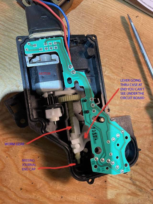
The motor and its gear were loose, the circuit board was popped up from its mounting, and the little end journal cap on the worm gear was missing (took me a while to figure out what the little plastic cup laying in the bottom of the case was for).
The lock motor and its gear are on the left. They drive another ring gear on a worm gear, at centre of pic. The worm gear moves the white plastic lever on the right that goes thru the case as the female portion of the screw on the bracket I needed to orient. So the motor moves the worm gear, which moves the white lever, which moves the bracket on the outside of the case, which moves the lock selector in the mechanical half. (Note a limit switch mounted to the circuit board that is actuated by part of the white plastic bits moved by the worm gear.)
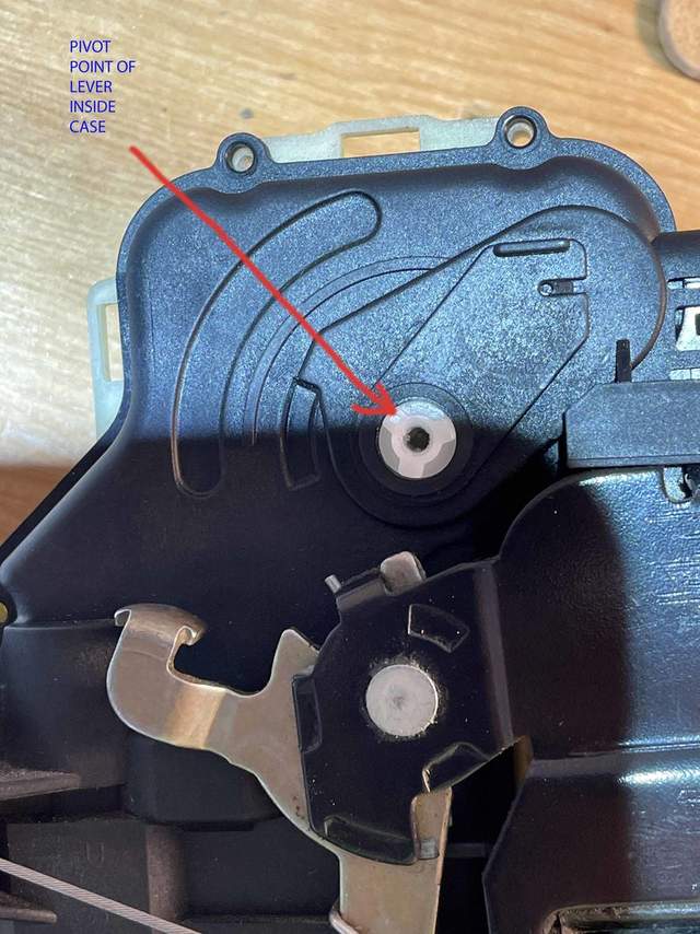
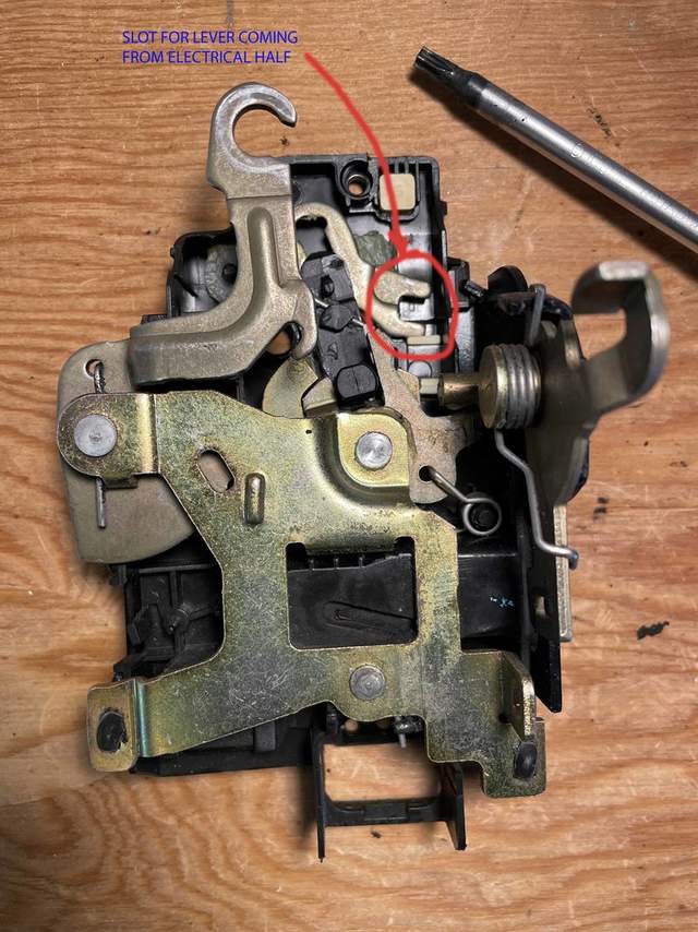
Once I got the journal cap back on and the motor and worm gear back in place, I had to make sure the white lever was in the right place for me to reattach the exterior bracket. On the interior side of the cover there is an oval that indicated the run of the white plastic on the worm gear, so I set the white plastic so it was in the center of the run, to give me an idea of how to mount the bracket once I had the electrical case closed up again. The bracket has to sit such that the arm going into the mechanical half sits in the slot there. (In retrospect, since there are only 3 tabs on the exterior of the white plastic, it would actually have been hard to get it wrong and have the lock lever on the bracket not be pointing to the right place in the mechanical half. As long as the bracket lever is pointing in the general direction of its counterpart slot in the mechanical half, it will allow you pick the right way to mount the bracket on the 3 tabs.)


Once the bracket arm was aimed in the right direction, the bracket could be screwed down in the correct orientation on the 3 tabs. Then the two halves of the module could be reunited, the two tabs snapped in place and the two screws installed. When putting together the two halves don't pull the lever arm that attaches to the door handle too far or you'll be taking the mechanical half apart yet again...
Next there is the spring to reinstall. Make sure this spring is in the right spot; apparently if you don't you could run into a number of problems. The spring snaps out of this spot with the first actuation of the door handle, so I think it's just there to ensure that when the door handle is connected to the module the lever arm is sitting in exactly the correct position.

Reattach the interior latch cable and snap on the retainer.
Attach electrical connector, slip module back into door, fasten the two exterior screws, and connect to door handle.
Reassemble rest of door.