Go Back   986 Forum - The Community for Porsche Boxster & Cayman Owners > Porsche Boxster & Cayman Forums > Performance and Technical Chat

Post Reply
 
LinkBack Thread Tools Display Modes
Old 04-01-2017, 01:39 PM   #1
Beginner
 
Jamesp's Avatar
 
Join Date: Mar 2013
Location: Houston
Posts: 1,659
Garage
Need Professional Help Diagnosing with Durametric Data

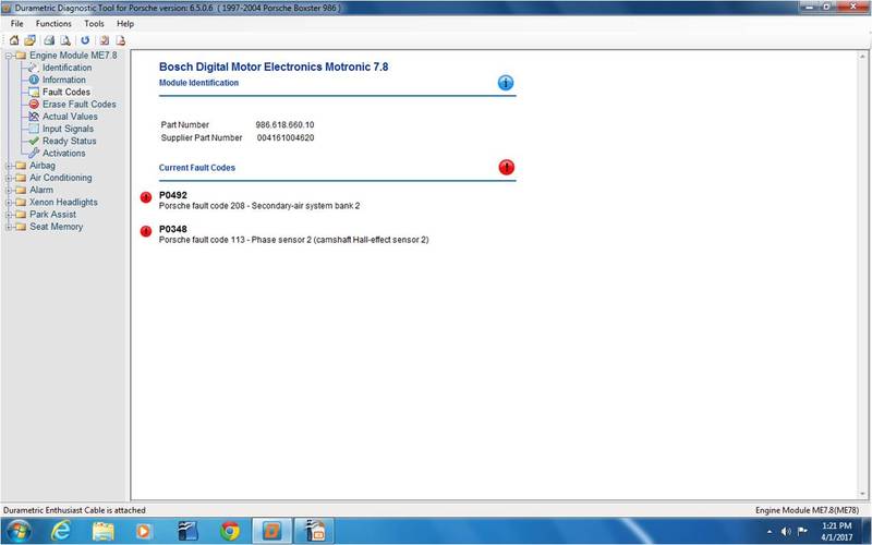
I have had a problem with the secondary air system bank 2 for years now in my 2003 manual S. Here are some specifics:

The secondary air pump runs in the morning if it is cold

I've replaced the Secondary air change over valve, the secondary air cutoff valve and the secondary air check valve. I was hoping carpet bombing would work, it didn't.

I pulled a vacuum through the secondary air check valve with a vacuum pump and it held vacuum.

I pulled a vacuum on the long plastic hose for the fuel system regeneration valve and it held vacuum

I pulled a vacuum on the hose leading to the fuel system regeneration valve and it held vacuum.

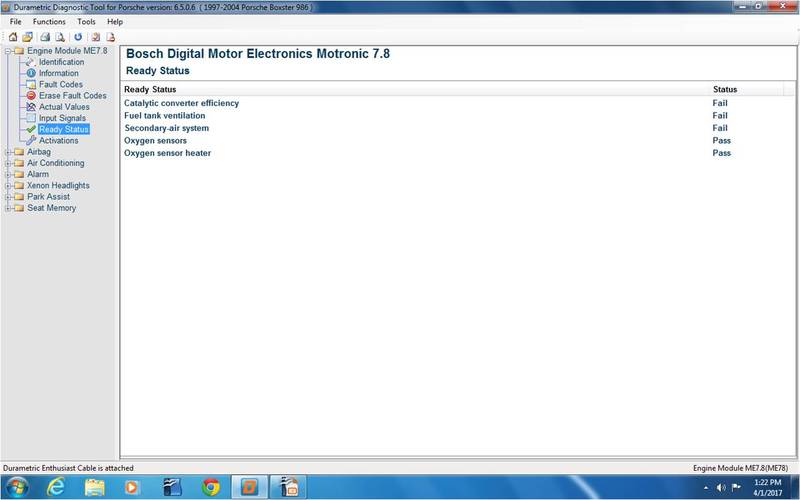
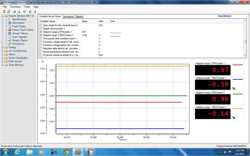
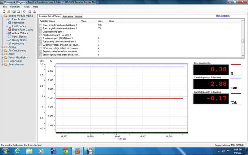
Using my scant Durametric knowledge here is some screen shot data I'm hoping will be useful. If additional data is needed let me know and I'll fetch it.


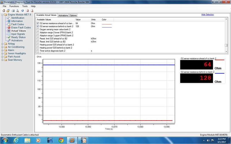
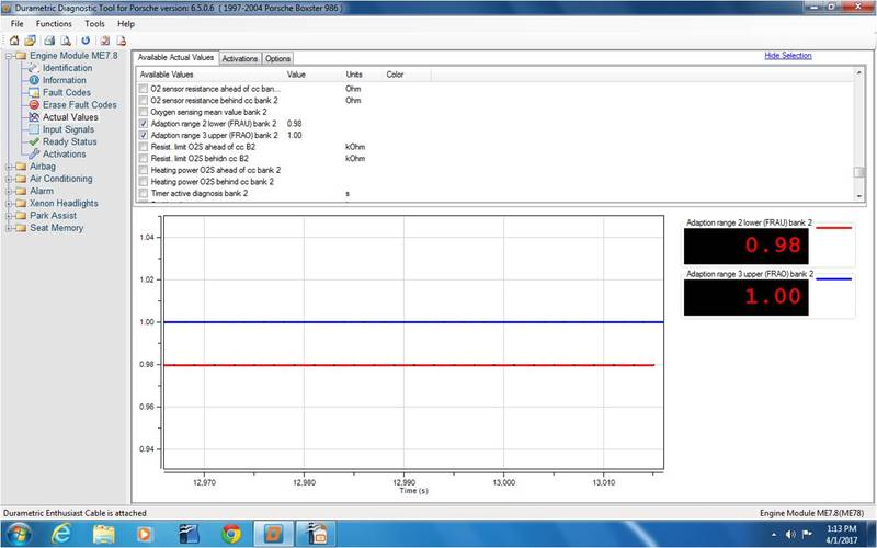
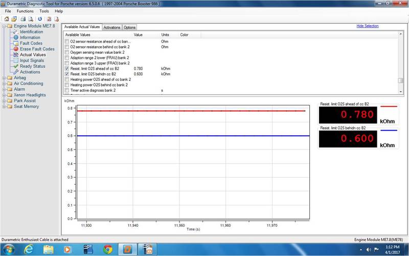
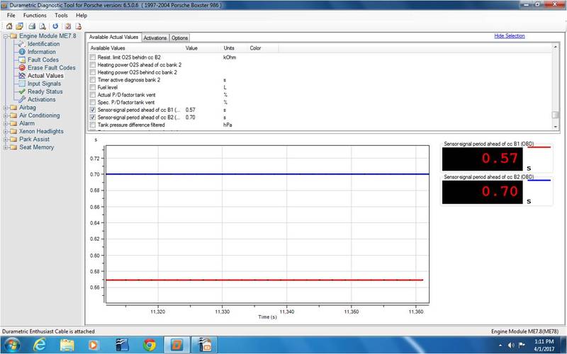
Any insight using the above data would be greatly appreciated. I'd love to better understand what the Durametric is telling me, but I'm not there yet.

__________________
2003 S manual
Jamesp is offline   Reply With Quote
Old 04-01-2017, 01:55 PM   #2
Custom User Title Here
 
particlewave's Avatar
 
Join Date: Mar 2012
Location: Ft. Leonard Wood
Posts: 6,163
Garage
Do the later models have a valve between the banks? In mine, there are the 3 valves, then a distributor splits the air between the banks.

If it's the same, I would think the distributor or O2 sensor related.
Sorry, not much help with the Durametric readouts...still learning mine.
particlewave is offline   Reply With Quote
Old 04-01-2017, 03:24 PM   #3
Beginner
 
Jamesp's Avatar
 
Join Date: Mar 2013
Location: Houston
Posts: 1,659
Garage
I don't know the system end to end, yet. I have a feeling I'll be getting familiar with it. Is there a system on the car less inspiring than secondary air injection? I'm hoping the smart folks on the forum can chime in particularly if they have seen this before and know how to track it down.
__________________
2003 S manual
Jamesp is offline   Reply With Quote
Old 04-01-2017, 04:07 PM   #4
Custom User Title Here
 
particlewave's Avatar
 
Join Date: Mar 2012
Location: Ft. Leonard Wood
Posts: 6,163
Garage
The system is actually very simple. The air pump feeds air through the change over valve, which is opened by the vacuum provided by the electronic change over valve, then passes through the one-way check valve into the distributor where it flows straight down into bank 1 and into a hose that leads to bank 2. Maybe the distributor is blocked or the bank 2 hose is blocked, disconnected or cracked/leaking.

Looking at your Durametric values and codes, I suspect something else is going on. Hopefully someone can translate.


Last edited by particlewave; 04-01-2017 at 04:19 PM.
particlewave is offline   Reply With Quote
Old 04-02-2017, 07:08 AM   #5
Beginner
 
Jamesp's Avatar
 
Join Date: Mar 2013
Location: Houston
Posts: 1,659
Garage
ParticleWave - Thank you very much for the diagram and explanation of the system. You clearly have a better understanding of the SAI system than I. I'd like to run my limited understanding of the system past you (and other knowledgeable members of the forum) so you can correct and add to the understanding of the system for myself and other forum members.

The SAI pump only runs if the engine is cold, and the ambient temperature is less than 70(?) degrees Fahrenheit. It only runs for about 90 seconds after engine start up in those circumstances. This is strictly for emission control.

The pump supplies air through the valve system in the diagram below (this diagram can change between model years) to engine bank one and bank 2. The air runs through passages in the heads directly to the exhaust manifolds. Bank 1 is on the right side of the engine viewed from the back of the car, and bank 2 is on the left.

The feedback system for the SAI is through the O2 sensors.

Another clue to the SAI fault in my car is that is faults out when the SAI should not be active. I reset the faults while the car is hot, and the ambient temperature is above 80 degrees F and the car still throws the SAI CEL.

What in the feedback loop would throw the CEL? Is is possible an O2 sensor is at the root of it?

I'd like to figure out how to use the Durametric to chase down the culprit instead of engaging in more carpet bombing with semi-random parts through frustration.
__________________
2003 S manual
Jamesp is offline   Reply With Quote
Old 04-02-2017, 08:08 AM   #6
Registered User
 
Join Date: Feb 2005
Location: It's a kind of magic.....
Posts: 6,277
OK, let's start with the basics, as in what the codes mean, so from the OBD II manual for your car:

P0492 Secondary Air Injection System, Bank 2 - Insufficient Flow

Possible cause of fault

- Electrical fault in power supply or line between relay and secondary air injection pump

- Secondary air injection pump relay mechanically faulty

- Mechanical fault in electrical secondary air valve

- Pneumatic secondary air valve faulty/sluggish

- Electrical fault in secondary air injection pump

- Mechanical fault in secondary air injection pump or secondary air injection pump blocked

- Vacuum system leaking

- Air hose to secondary air injection pump slipped off or constricted

P0348 Camshaft Position Sensor 2 – Above Limit

Possible fault cause
- Short circuit to B+

It is likely that the codes are related, especially as the P0348 indicates a possible electrical short, as does the P0492.
__________________
Anything really new is invented only in one’s youth. Later, one becomes more experienced, more famous – and more stupid.” - Albert Einstein

Last edited by JFP in PA; 04-02-2017 at 09:17 AM.
JFP in PA is offline   Reply With Quote
Old 04-02-2017, 09:52 AM   #7
Beginner
 
Jamesp's Avatar
 
Join Date: Mar 2013
Location: Houston
Posts: 1,659
Garage
Thank you very much JFP, I was hoping you would weigh in. Thanks for taking the time to provide the details behind the codes. I was looking to purchase documentation containing detailed references to the codes with fault trees, but I don't know which documentation to purchase. Can you provide a reference?

As for chasing a short, I have the older shop manuals with wiring diagrams, but not a 2003. Is there reference material you would recommend?

I just got through running the car to make Durametric screen shots and Porshe code 80 also popped up - secondary air system bank one. That secondary air system is a pain in the rear, or perhaps better stated the middle.

Thanks again,

Jim
__________________
2003 S manual

Last edited by Jamesp; 04-02-2017 at 09:56 AM.
Jamesp is offline   Reply With Quote
Old 04-02-2017, 10:34 AM   #8
Registered User
 
Join Date: Feb 2005
Location: It's a kind of magic.....
Posts: 6,277
Quality documentation is going to be hard to come by; Porsche stopped printing anything more than 10 years ago, and the only two ways to get current updated and legitimate info is either through Porsche's online subscription service (PIWIS TSI), or with a PIWIS unit itself.

A second route, albeit with copyright infringement baggage, would be to contact "Porschelibrarian" on the RennTech site; he sells such information.

Good luck.
__________________
Anything really new is invented only in one’s youth. Later, one becomes more experienced, more famous – and more stupid.” - Albert Einstein

Last edited by JFP in PA; 04-02-2017 at 10:38 AM.
JFP in PA is offline   Reply With Quote
Old 04-02-2017, 12:51 PM   #9
Registered User
 
Join Date: Dec 2014
Location: Ashland, OR
Posts: 48
"As for chasing a short, I have the older shop manuals with wiring diagrams, but not a 2003. Is there reference material you would recommend?"

I have an '03 and was able, with some patient analysis, to utilize the wiring diagrams in the Bentley manual for the 2001 year to isolate and trace a P0343 code, which is the same "cam position sensor, short to B+, above limit" except for Bank 1, that you have for Bank 2 (P0348)
Although not exactly the same for year '03, the diagrams from '01 are close enough that by identifying the wire colors involved in the circuit to the DME, I was able to figure out that my short was due to the Cam Sensor itself being faulty.
luckyed7711 is offline   Reply With Quote
Old 04-02-2017, 01:27 PM   #10
Beginner
 
Jamesp's Avatar
 
Join Date: Mar 2013
Location: Houston
Posts: 1,659
Garage
For some reason I'm hard on cam sensors. Bank one failed shortly after the engine was rebuilt. I replaced it with the cheaper FAE brand. I pulled the bank 1 connector yesterday and the electrical connector was full of engine oil. I ordered two Bosch sensors from Pelican.
__________________
2003 S manual
Jamesp is offline   Reply With Quote
Old 04-05-2017, 05:57 PM   #11
Beginner
 
Jamesp's Avatar
 
Join Date: Mar 2013
Location: Houston
Posts: 1,659
Garage
First a big THANK YOU! to the folks who provided the information to put me on the right track to finally (I think!) solve the SAI fault in my Box.
Since I did a bit of extracurricular studying on this one I thought I'd write it up and share the wealth. I read everything I could find on the SAI and even read through the Bosch "Gasoline-engine management Technical Instruction ME-Motronic engine management". Turns out Porsche doesn't design the engine management system, Bosch designs it for Porsche - other car companies too. Who knew?
Enough trivia, on to what Secondary Air Injection system (SAI) does. The SAI is designed primarily to control pollution at start up when the engine is cold, and the ambient temperature is below a predetermined limit. I think that limit is 70F but don't quote me on that. In cooler conditions, older carburetor equipped cars had a choke, which for you younger kids was a restriction plate kind of like a second throttle plate at the top of the carb that closed using a bimetal coil in the cold, and opened when the bimetal coil got hot. It's the same way those old timey round thermostats work. This makes the mixture rich enough to burn when the engine and air are cold. Turns out all engines need that rich mixture on a cold start including fuel injected engines. Fuel injected engines get that rich mixture by simply injecting more fuel. The problem is, that rich mixture does not burn completely and also has a lot of nasty polluting components in the combustion products due to the lack of air when it burns in the cylinder. Enter the SAI.


The SAI is made up of parts you can see, the pump, along with a system of hoses and valves to control the air when the pump is running. There is a part you can't see, which is comprised of holes running from the top of the head to the exhaust manifolds - those are the little holes and galleys you see if you remove your exhaust header. There is also a dedicated electrical system to run the pump and actuate the valves.
The SAI pumps air straight through the passages in the heads into the exhaust manifold where is meets up with all the nasty unburned fuel and pollutants to provides the oxygen they need to complete combustion. Then that "reburned" exhaust gas passes by the upstream O2 sensor in front of the catalytic converter, and then the downstream O2 sensor after the catalytic converter. One of the O2 sensors, I believe it is the downstream sensor (again, don't quote me) determines if the mixture is stoichiometric. Stoichiometric means the fuel and air mixture balance so all of the air is used and all of the fuel is used. The upshot is that most of the bad actor pollutants are combining with the SAI air to form less harmful compounds such as water and CO2. This also keeps nasty compounds and unburned fuel from fouling your cats. The mixture band where all this good stuff happens is very narrow, which means the SAI pretty tightly controlled by the O2 sensor which makes the whole system kind of finicky.
If you've read through all that, it suddenly makes sense why a vacuum leak would throw the system off. The mixture the car *thinks* it has is being leaned out by the vacuum leak, put that on top of the O2 sensor trying to control the SAI to a narrow band and at some point the system gives up and throws a CEL. It also explains why any deviation on the SAI side causes the whole scheme to crater. Hello CEL!
So how to go about diagnosing an SAI code when the code essentially says, "Something in your SAI is broken"? Start by not doing what I did. I hotwired the SAI pump and it ran, so far so good, I then decided I'd change out the "most likely" components and hope for the best. That was pretty stupid, I had to bust my knuckles and disassemble lots of stuff on the engine to spend money on and change parts that were perfectly good.
If I were to do it again this is what I would do in the following order:
Pull the black and white check valve - make sure it's working by blowing air though it both ways. if it doesn't stop airflow in one direction it's shot. Put it back in the way it came out - that is critical.
Check the intake manifold and hoses for vacuum leaks
Check the crank case for vacuum leaks
Check the 40 amp fuse in the trunk
Check the 40 amp relay in the trunk
Buzz out wires using schematic and ohm meter
Jumper the pump to make sure it runs
Only after the above would I move to other SAI components.
There are lots of ways on YouTube to check for vacuum leaks. I've used several methods and find the cheap cigar method to be the cheapest and quickest. You need a cheap cigar and about 3 feet of vacuum hose to inject smoke at your chosen fitting. I chose to use the 1/4 inch(ish) fitting between the AOS and throttle body and did the following
1) Set the engine to TDC. This closes all of the intake and exhaust valves to isolate the intake manifold and limit leaking into the cylinders
2) Remove the plastic intake pipe from the throttle body and slip a piece of 3 or 4 mil plastic sheet between the throttle body and intake tube. Snap the tube back on to seal the intake inlet.
3) Attach the vacuum tubing to the manifold fitting of your choice
4) Light a cheap cigar and blow the smoke into the intake manifold
5) for the SAI components and vacuum reservoir behind the SAI check valve I used a small vacuum pump showing no leak. One could remove the check valve and smoke check that if no vacuum pump is available
I was surprised how tight the manifold was. After about a lungful of air it was like trying to blow up a very difficult balloon and held pressure for about 2 minutes before leaking down. I did not see any smoke anywhere using a light.

Checking the crankcase was a similar exercise using the corner of a heavy duty trash bag with (white) electrical tape used to seal it and hold it in place. It yielded similar results


I've read that the fuse (yellow rectangle) in the trunk was on the firewall. Mine was in the left rear fender under the trunk liner and in perfect condition. The Relay / fuse holder slides out on rails.


The Relay is near the fuse. Mine is clearly fried. I removed it and tried to cycle it with the car battery and it is dead as a coffin nail. * We have a winner!* Woo Hoo!!!!!!


If I were still trouble shooting the next thing I would do is jumper the SAI pump to check operation. In my 2003 the red and black wire is positive.
The reason I would troubleshoot in the order given, is there little disassembly involved. If everything discussed so far passes, then it is time to start taking things apart, and that won't be easy due to lack of working room.
Had I not found the bad relay in the trunk I would proceed by removing the right hand side of the intake manifold and go from there. I have removed that with the engine in the car and it's not fun. When I replaced the SAI shutoff and change over valves I opted to remove the alternator and work under the manifold which was super tight but possible YMMV. Different years have different SAI components so this may not be possible on all models.
After dis-assembling to the SAI and before taking it apart, I would first pull a vacuum on the changeover valve and shut off valve (with a hand vacuum pump), then actuate the changeover valve with 12 volts while blowing into the air pump hose to see if the changeover / shutoff valves were working. If they are then it's time to smoke test the SAI circuit - hope those cigars are handy.
There is one more fault from my research apparently not uncommon on 993s, I've found one high mileage 986 having it. That is the SAI passages in the heads clogging with carbon. If everything else fails, and air is not going through the SAI through the exhaust when you smoke test it, drop the exhaust headers and use a long thin sharp wire to clean the carbon out of the SAI passages in the head.
Also I'd like to thank the folks at Pelican Parts who make this forum possible.

__________________
2003 S manual
Jamesp is offline   Reply With Quote
Old 04-06-2017, 05:52 AM   #12
Registered User
 
Join Date: Dec 2009
Location: Orange County, CA
Posts: 1,848
I love the picture of the pelican..
Gilles is offline   Reply With Quote
Old 04-06-2017, 08:47 AM   #13
Registered User
 
Join Date: May 2014
Location: S.California
Posts: 2,027
James - excellent write up of the diagnosis .Thank you for sharing.So often such Threads just die or the OP says "it was 'the' relay".
So your problem was 'just' the faulty SAI pump motor relay ? Part #: 993-615-115-01
http://www.pelicanparts.com/catalog/SuperCat/986M/POR_986M_FULEMI_pg3.htm

No vacuum leaks, no vacuum component failures?
I ask because one of the causes of relay failure is a defective SAI pump that draws too much current because the bearings are worn or it is literally falling apart inside the case.. The pump can be rebuilt but it is tedious. More in Search.http://rennlist.com/forums/996-forum/735878-sai-repair-diy.html
How did the SAI pump work with a faulty relay ? Because you hot wired it ?
btw ,if that relay is like mine, it is an oddball pin orientation - in case others think a generic will work.
Considering the frequency with which this subject comes up, your diagnosis will be very helpful to other Forum members.
It certainly makes the ROW reflash seem appealing -if that is still available?
ECU Doctors used to offer it for $500.
http://www.ecudoctors.com/porsche-boxster-ecu-performance-tuning-flash-2.html

Last edited by Gelbster; 04-06-2017 at 09:04 AM.
Gelbster is offline   Reply With Quote
Old 04-06-2017, 03:41 PM   #14
Beginner
 
Jamesp's Avatar
 
Join Date: Mar 2013
Location: Houston
Posts: 1,659
Garage
Quote:
Originally Posted by Gelbster View Post
James - excellent write up of the diagnosis .Thank you for sharing.So often such Threads just die or the OP says "it was 'the' relay".
So your problem was 'just' the faulty SAI pump motor relay ? Part #: 993-615-115-01
Porsche Boxster (1997-2004) - Emissions Equipment - Page 3

No vacuum leaks, no vacuum component failures?
I ask because one of the causes of relay failure is a defective SAI pump that draws too much current because the bearings are worn or it is literally falling apart inside the case.. The pump can be rebuilt but it is tedious. More in Search.http://rennlist.com/forums/996-forum/735878-sai-repair-diy.html
How did the SAI pump work with a faulty relay ? Because you hot wired it ?
btw ,if that relay is like mine, it is an oddball pin orientation - in case others think a generic will work.
Considering the frequency with which this subject comes up, your diagnosis will be very helpful to other Forum members.
It certainly makes the ROW reflash seem appealing -if that is still available?
ECU Doctors used to offer it for $500.
ECU Performance Tuning for Porsche Boxster ECU DME - Specialized ECU Repair
I believe the failure is contained within the relay. The SAI pump pulls quite a bit of current. The 40 amp fuse was good and I'd hope that would go before the relay if the pump were to blame.

The relay had seen an extreme amount of heating on the connector blade that is nearest the relay contact pads. On pulling the relay apart the pads and the metal around them showed signs of extreme heat. The connector blade nearest the contact pads is not only discolored from heat, but is dead soft from annealing. I've never seen anything like it. You can easily bend the connector blade with your fingers into a "C" shape. I doubt the other blades could be bent like that with needle nose pliers. I think the contact pads became contaminated with carbon/corrosion and the resistance increased until something inside the coil circuit failed open, perhaps a solder joint I cannot see it though.

I have heard the fan run on cold mornings, but not for the last couple of years because we've had few cold mornings. I did jumper the fan and it spins right up and sounds sweet.

Gilles, that is the only time I've seen a pelican on my deck to I snuck up and snapped a picture. What is really interesting is the gulf osprey in the background on the railing of the neighbors pier
__________________
2003 S manual

Last edited by Jamesp; 04-06-2017 at 03:44 PM.
Jamesp is offline   Reply With Quote
Old 04-06-2017, 03:49 PM   #15
Registered User
 
Join Date: May 2014
Location: S.California
Posts: 2,027
The relay condition sounds awful. The P.O. ran with a 50 A fuse maybe- before the SAI pump failed and he replaced it ?
Makes me wonder about trying a 30 A fuse to avoid relay damage ,not to mention the wiring harness from the Pump to the trunk.
Gelbster is offline   Reply With Quote
Old 04-11-2017, 05:27 AM   #16
Beginner
 
Jamesp's Avatar
 
Join Date: Mar 2013
Location: Houston
Posts: 1,659
Garage
Well the car was all put back together with a new 40 amp relay, everything seemed good and at 50 miles it throws the bank 1 and bank 2 SAI codes again. :ah:

Checked for voltage at the 40 amp fuse in the trunk and it is there.

Jumpered the 40 amp relay in the trunk and the SAI pump ran like a champ.

Checked the new 40 amp relay out of the car confirming switching and continuity.

Pulled the SAI hose and verified the fan is pushing air.

Video inspected the vacuum connections in the system and they all look good - they also hold vacuum using a hand operated vacuum pump.

Video inspected the electrical connection on the change over valve and it is connected and looks good (dusty but not oily).

So moving forward, and trying not to pull the flipping thing apart I figured I'd ask the Forum for their thoughts before I do some serious damage.

So here's the plan:

I've pulled connectors 1 through 4 from the main computer in the trunk.

The power from the SAI changeover valve appears to be coming from Connector 2 pin 30 from the Cartronics computer in the trunk. I'd appreciate it if someone can confirm that for a 2003. My documentation is for a 2000 and I'd hate to let the smoke out of something.

My plan is to probe pin 30 with 12 volts to manually actuate the changeover valve.

I can supply vacuum to to the system with the manual pump at the check valve.

At that point the shut off valve should open (may need to refresh the vacuum at this step)

With the shut off valve in the open position blow into the tube from the SAI pump to check for free air flow.

Jumper the SAI pump and note RPM changes with the hose connected, disconnected and with the changeover valve open and closed

If no free air flow or no SAI RPM change while manually configuring different system states work to inspect change over valve, shut off valve, passages in head etc.

Thoughts?
__________________
2003 S manual
Jamesp is offline   Reply With Quote
Old 04-11-2017, 08:33 AM   #17
Registered User
 
Join Date: May 2014
Location: S.California
Posts: 2,027
"everything seemed good and at 50 miles it throws the bank 1 and bank 2 SAI codes again
Obviously this is not the regular SAI problems.
Now that you've become an involuntary expert on the subject- the SAI system should not be running 50 miles after a start. So what happened then to produce code? A bump+loose connection? Fault to ground ? Such a transient fault would set a Pending Code and the next bump would add to the store of Pending codes and eventually the CEL would illuminate on the dash.
I ask this seemingly silly question because you've tested the system physically and electrically very carefully many times.
After the car has warmed up, can you wiggle any of the harness/connectors to produce the CEL ? Unless we can reproduce the situation that prompts the CEl we're just flailing.
The other more intelligent(?) option is to check continuously for Pending Codes whenever you are driving. Maybe there was a Pending SAI code set at start up but it requires reconfirmation before the light on the dash illuminates(at 50 miles) ? Or could this be just a Drive Cycle readiness process and it will eventually become 'ready'.
Good luck !

Last edited by Gelbster; 04-12-2017 at 08:47 AM.
Gelbster is offline   Reply With Quote
Old 04-12-2017, 08:36 AM   #18
Custom User Title Here
 
particlewave's Avatar
 
Join Date: Mar 2012
Location: Ft. Leonard Wood
Posts: 6,163
Garage
Quote:
Originally Posted by Gelbster View Post
"everything seemed good and at 50 miles it throws the bank 1 and bank 2 SAI codes again
Obviously this is not the regular SAI problems.
Now that you've become an involuntary expert on the subject- the SAI system should not be running 50 miles after a start. So what happened then to produce code? A bump+loose connection? Fault to ground ? Such a transient fault would set a Pending Code and the next bump would add to the store of Pending codes and eventually the CEL would illuminate on the dash.
I ask this seemingly silly question because you've tested the system physically and electrically very carefully many times.
After the car has warmed up, can you wiggle any of the harness/connectors to produce the CEL ? Unless we can reproduce the situation that prompts the CEl we're just flailing.
The other more intelligent(?) option is to check continuously for Pending Codes whenever you are driving. Maybe there was a Pending SAI code set at start up but it requires reconfirmation before the light on the dash illuminates(at 50 miles) ? Or could this be just a Drive Cycle readiness process and it will eventually become 'ready'.
Good luck !
SAI fault will not immediately trigger a CEL.


Quote:
Originally Posted by Jamesp View Post
So here's the plan:

I've pulled connectors 1 through 4 from the main computer in the trunk.

The power from the SAI changeover valve appears to be coming from Connector 2 pin 30 from the Cartronics computer in the trunk. I'd appreciate it if someone can confirm that for a 2003. My documentation is for a 2000 and I'd hate to let the smoke out of something.

My plan is to probe pin 30 with 12 volts to manually actuate the changeover valve.

I can supply vacuum to to the system with the manual pump at the check valve.

At that point the shut off valve should open (may need to refresh the vacuum at this step)

With the shut off valve in the open position blow into the tube from the SAI pump to check for free air flow.

Jumper the SAI pump and note RPM changes with the hose connected, disconnected and with the changeover valve open and closed

If no free air flow or no SAI RPM change while manually configuring different system states work to inspect change over valve, shut off valve, passages in head etc.

Thoughts?
Sounds like s solid plan. Can the electronic changeover valve and air pump be triggered by the Durametric with the engine not running? I thought I read that they could, but have not played with my Durametric much yet.

Guess what I got yesterday...p0410 and p1411! Yay! :dance:
I suspect my changeover valve cleaning didn't take, though it lasted a few months.
particlewave is offline   Reply With Quote
Old 04-12-2017, 08:46 AM   #19
Registered User
 
Join Date: May 2014
Location: S.California
Posts: 2,027
This is why I wrote "Pending Code" -twice.
Good luck with the diagnostics. Awful access ,much sympathy.
Before you dig in, may be worth running the engine longer to see if any other Pending Codes appear. I suggest this because it would be a pity to have to do over.
If you remove the SAI pump, run it on the bench for 5 minutes to see if it makes distressed noises or becomes hot. The internals of these pumps have issues. There is a diy to refurb and lube it.Dismantling the pump part is easy but the motor itself is staked. So if the motor is getting hot ,that may become a failure eventually.
On mine you can run the SAI pump with key on engine off using Durametric. If you try the valves - you can hear them make a muffled click.

Last edited by Gelbster; 04-12-2017 at 08:54 AM.
Gelbster is offline   Reply With Quote
Old 04-12-2017, 09:05 AM   #20
Custom User Title Here
 
particlewave's Avatar
 
Join Date: Mar 2012
Location: Ft. Leonard Wood
Posts: 6,163
Garage
BTW, the changeover valve is pin 30. Not sure what this "connector 2" is that you keep talking about, but it's on connector "C".
C30, to be exact.

Something I've considered to simplify things a tiny bit is eliminating the vacuum and electronic changeover valve. As it is, the system requires air pressure, electricity and vacuum. Why not just feed the electronic changeover valve signal to a relay that powers a solenoid operated changeover valve?
I may try this...

Thanks for the info, Gelb


Last edited by particlewave; 04-12-2017 at 09:18 AM.
particlewave is offline   Reply With Quote
Post Reply


Posting Rules
You may not post new threads
You may not post replies
You may not post attachments
You may not edit your posts

BB code is On
Smilies are On
[IMG] code is On
HTML code is On
Trackbacks are On
Pingbacks are On
Refbacks are On


All times are GMT -8. The time now is 06:57 PM.


Powered by vBulletin® Version 3.8.7
Copyright ©2000 - 2024, vBulletin Solutions, Inc.
Content Relevant URLs by vBSEO 3.6.0
Copyright 2024 Pelican Parts, LLC - Posts may be archived for display on the Pelican Parts Website -    DMCA Registered Agent Contact Page