Folks,
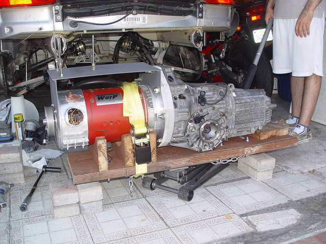
As some of you are aware, I am converting my '04 Boxster to Electric. The project is going slow but progressing. At this time I have the drive train assembled and mounted using the TX mounts and the wheel hubs are connected. See pic.
I am planning to use the stock engine mount to support/mount the DC motor in the front. The next part of the project I am working on is to make the custom bracket to connect/mount the DC motor to the engine mount carrier.
To make the custom bracket I need to know the exact forward/backward and lateral position of the drive train. Note I don't have the engine there so don't know exactly where the TX should be sitting (the Tx mounts allow for small movement as per design).
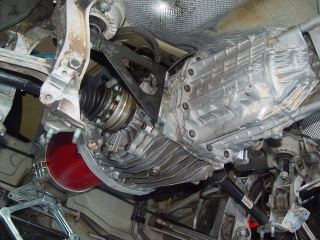
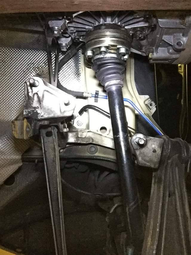
I have taken pictures of the TX and TX mounts and the hub from below. Here are some questions:
- Do the Tx mounting brackets (hydraulic triangular ones) need to be exactly perpedicular to the Tx surface exactly behind the rotating parts to the which the hubs attach?
- Do the same need to be perpendicular to the surface of the solid brackets i.e. side sections - to which the mounts are fixed?
- Would anyone have or can take a pic from the bottom from approx the same position so I can eyeball it?
- Is there another way to ascertain the 3 dimensional position of the TX where it needs to be?
- Would someone tell me the distance between the bottom part of the TX flange and the cross member (not yet fitted in the pics). I could fit the cross member and establish vertical height from that..
- Does the center of TX need to align with the center of the engine mount? I would assume so, just confirming...
I just need to get a approx way of knowing if my TX is in proper position as the tock TX needs to be.
Appreciate any help.
Also a lot of people have asked me for updates on how my project is going. I need to get to updating my thread to keep you guys updated. I promise I will start updating that thread...:-)
Cheers.


 Growly Grannis/Sex stallion
 2004 Porsche Boxster S
 2004 Porsche 996 Targa
 Linear Mode


