Go Back   986 Forum - The Community for Porsche Boxster & Cayman Owners > Porsche Boxster & Cayman Forums > Performance and Technical Chat

Post Reply
 
LinkBack Thread Tools Display Modes
Old 02-17-2014, 11:53 AM   #1
Beginner
 
Jamesp's Avatar
 
Join Date: Mar 2013
Location: Houston
Posts: 1,659
Garage
First, I have to say the for me, getting it wrong and then getting it right is part of the DIY fun. Those lessons stick, at least with me. Nothing like experience as a teacher.

Post 69 in this string from Jsceash (thanks Jsceash!) has a good blow by blow to check the timing. Another string is a good idea as this one wanders all over the place.

The end point you are looking for is:

With your engine locked at TDC the cam timing tool will go into both milled slots in only a single set camshafts (bank 1 or 2 ) at the same time. Roll the 360 degrees and lock it at TDC again. Now the camshaft tool will fit the camshaft slots on the opposite bank.

Things I found helpful to know:

Which hole is TDC in the crank pulley
Check the cams milled slot alignment with the tensioners in the engine
Only roll the engine in the direction it runs in (clockwise)
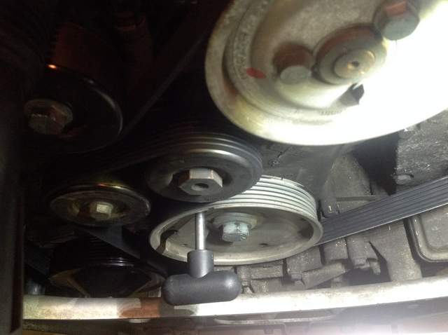
Use the crank pulley bolt to counter torque torquing operations
The cams will self seek the TDC position as the cams are all sitting on their cam circles at this point - this is important because if you don't have the engine at TDC, due to valve spring forces the cams/ valves will try to get there with or without crankshaft rotation.

How to break things:

Torquing with the crankshaft or the camshafts locked with their locking tools. These are positioning aids, not locks for torquing. The exception is first pass low torque on the exhaust camshaft sprocket

Taking the valve covers off without the proper tools to hold the camshafts or with the engine not at TDC

Getting the valve timing wrong - see the first sentence in this post for that.


If I were tackling this, I'd check the valve timing with the engine in the car, and if bank one was off, I would determine which way the chain needed to move (this is the chain by the IMS bearing) and see if it could be moved one link in the right direction. You may be designing a tool to do this. Necessity is the mother of invention. I have not looked closely at doing this but if that is where it slipped, then maybe it can be slipped back.

If that is a no go you are in for full up valve timing by removing the valve cover and setting the cam timing. Personally I would seriously consider removing the engine at this point just for access, but I have the tools and room to do this. If I did not I'd have to reconsider.

I'd appreciate other folks chiming in with suggestions or corrections, after all, it's what we do here.
__________________
2003 S manual

Last edited by Jamesp; 02-17-2014 at 12:03 PM.
Jamesp is offline   Reply With Quote
Old 02-17-2014, 05:16 PM   #2
Reebuck1
 
Join Date: May 2013
Location: Georgetown, SC
Posts: 210
Garage
pictures

Here are some pictures I did not get in last nights post

This started it all. Original IMS

Car has an Auto trans. so I am guessing this bearing cover is seeing some slight leakage and not clutch dust.

This is the original bearing I removed.


This shows engine at Bank 1 TDC with crank lock in.


Engine is presently in car so some of the pictures can not be taken "head on". But bank1 and Bank2 exhaust cam slots line up perfectly with the split between cam cover and main case. They seem properly positioned to me. I've been wrong before!

Bank 1 green plug removed shows Bank1 Exhaust cam position.


This picture show bank1 intake cam notch facing out board (away from the motor)
red pen pointing to notch. Note that the notch is slightly pointing UP from a dead level position. Is that a correct position?


The error code from the car at start up was P-1531 and referenced Bank1. But to me everything in Bank1 looked close. What is the general thinking?

I will send another post with more pictures so I do not exceed limits for this post.
Reebuck1 is offline   Reply With Quote
Old 02-17-2014, 05:54 PM   #3
Beginner
 
Jamesp's Avatar
 
Join Date: Mar 2013
Location: Houston
Posts: 1,659
Garage
From what I've seen your timing looks off between the camshafts. Best advice I have is remove the engine from the car again, and carefully allocate the timimng again step by step. I had to do that. Then roll the engine several times when it is all back together checking the valve timing each revolution before putting it back in. I did that too. What bothers me is you have camshafts connected by a chain and I don't undersand how the camshafts could be off with respect to each other unless your variocam is playing up with you, or if you had the cams out and did not allocate them correctly. I'm a rookie, others on the forum have more experiance than I, and may have better insight.
__________________
2003 S manual
Jamesp is offline   Reply With Quote
Old 02-17-2014, 05:45 PM   #4
Reebuck1
 
Join Date: May 2013
Location: Georgetown, SC
Posts: 210
Garage
More pictures

Back to bank 1. This afternoon I checked the bank 1 solenoid to ensure it was functioning. I disconnected the solenoid from the harness and used a small 9V. battery to see if I could hear it click. I clicked it several times and it worked every time. I am not sure it would tell me if it were stuck but I could hear slight movement. I did not check wiring on the other side of the plug back to the main wiring harness. This shows picture shows the solenoid. It appeared to be slightly leaking before I cleaned it.


Moving to Bank 2. This is the exhaust cam slot showing vertical position with the crank still locked in the same position as when I checked bank 1. It was difficult to take pictures on this side but the exhaust slot matched the case split.


This picture shows the intake cam slot on Bank 2 pointing out board (away from the engine). Again difficult to see but appears ok to my untrained eye.


Thank you all for your help so far. Jake I'll buy your book as soon as its out and we all appreciate your comments. I think you should leave the chapter on wrecks in your book it may make us think twice.

OK guys what are your thoughts?
Reebuck1 is offline   Reply With Quote
Old 02-17-2014, 06:26 PM   #5
Engine Surgeon
 
Join Date: Aug 2008
Location: Cleveland GA USA
Posts: 2,425
That's a 5 chain engine. I'll bet your deviations have an underlying condition impacting them... You just aggravated it enough with the IMSR to wake them up.

This is why we check deviations before a process as part of the pre-qual and if the values are out of my spec, the engine doesn't get touched. If it is we end up where you are if they reach the CEL triggering point.

These wear horribly, even at lower mileage. I will bet you this is impacting the values and you probably didn't do anything wrong. You just "finger Fu***ed" it by touching it. The CEL would have set anyway.

Moral of the story? Assume nothing and quantify everything, including cam deviations before the process is done.
__________________
Jake Raby/www.flat6innovations.com
IMS Solution/ Faultless Tool Inventor
US Patent 8,992,089 &
US Patent 9,416,697
Developer of The IMS Retrofit Procedure- M96/ M97 Specialist
Jake Raby is offline   Reply With Quote
Old 02-18-2014, 04:51 AM   #6
Reebuck1
 
Join Date: May 2013
Location: Georgetown, SC
Posts: 210
Garage
Not the message I wanted to hear....But out comes the engine and trans and I'll try again. Jake I hear your message on the "some of the parts" and their relationship so I will pull the cam covers and look at guides and chains when I restart the process. When is your next class...I am interested. I really appreciate all the feed back. Can't say thanks enough.
Reebuck1 is offline   Reply With Quote
Old 02-18-2014, 06:43 AM   #7
Registered User
 
Join Date: Nov 2013
Location: Arizona
Posts: 90
I have a little experience with drive chains monitored by electronics, in printing presses. The computer in the printing press would time the chain movement and throw an error if it didn't like the chain movement.

There would be a number of possible things that could be wrong with the chain drive. The chains do stretch, mostly by wear in the roller links. Sometimes a link will get stiff and not bend enough. The teeth on the sprocket wear too, sometimes enough to cause an error. The sprocket teeth actually develop a hook shape when worn too much. And sometimes we couldn't find anything wrong with the chain, the computer just wanted a new one installed.

Another thing I wanted to add. Make sure you have cleaned and reconnected all grounding straps. It is easy to forget one or two of them, and your computer may not read sensors correctly with a missing or poorly connected ground strap.
__________________
It's all bad

Last edited by Walter White; 02-18-2014 at 07:07 AM.
Walter White is offline   Reply With Quote
Old 02-18-2014, 01:08 PM   #8
Reebuck1
 
Join Date: May 2013
Location: Georgetown, SC
Posts: 210
Garage
I cleaned and brushed all the grounding straps before engine install, so I'm guessing that is not it. I think Jake hit it when he suggested it is the SUM of wear on all the parts...5 chains...all cam teeth....CHAIN RAMPS....tensioners...etc. I believe I am going to have to tear down and remove cam covers and time the hard way. I do not think there is another way. If it is the sum of the parts the big question is which parts need to be replaced?? I am thinking about starting with chain ramps and maybe chains.
Reebuck1 is offline   Reply With Quote
Old 02-18-2014, 01:38 PM   #9
Beginner
 
Jamesp's Avatar
 
Join Date: Mar 2013
Location: Houston
Posts: 1,659
Garage
Quote:
Originally Posted by Reebuck1 View Post
I cleaned and brushed all the grounding straps before engine install, so I'm guessing that is not it. I think Jake hit it when he suggested it is the SUM of wear on all the parts...5 chains...all cam teeth....CHAIN RAMPS....tensioners...etc. I believe I am going to have to tear down and remove cam covers and time the hard way. I do not think there is another way. If it is the sum of the parts the big question is which parts need to be replaced?? I am thinking about starting with chain ramps and maybe chains.
Replacing the 3 main drive chains requires splitting the case. if you go that far you might as well do the bearings as well.
__________________
2003 S manual
Jamesp is offline   Reply With Quote
Old 02-18-2014, 04:25 PM   #10
Engine Surgeon
 
Join Date: Aug 2008
Location: Cleveland GA USA
Posts: 2,425
Pull the cam covers, remove the valve train and the lifter carriers. Look for cracks in the area under the lifter carrier while you are there and some coolant in the region is the best tell tale sign. Why? Because its guilty until proven innocent and you may as well look for whatever you can while you can.

Replace the 4/5 chains, have the lifters ultrasonically cleaned and inspect the cams for wear and lobe taper as well as the crowns of the lifters for wear. If all is well slap a new set of wear pads on the variorum servo and put it all back together. Problem solved.
__________________
Jake Raby/www.flat6innovations.com
IMS Solution/ Faultless Tool Inventor
US Patent 8,992,089 &
US Patent 9,416,697
Developer of The IMS Retrofit Procedure- M96/ M97 Specialist
Jake Raby is offline   Reply With Quote
Post Reply


Posting Rules
You may not post new threads
You may not post replies
You may not post attachments
You may not edit your posts

BB code is On
Smilies are On
[IMG] code is On
HTML code is On
Trackbacks are On
Pingbacks are On
Refbacks are On


All times are GMT -8. The time now is 12:23 AM.


Powered by vBulletin® Version 3.8.7
Copyright ©2000 - 2025, vBulletin Solutions, Inc.
Content Relevant URLs by vBSEO 3.6.0
Copyright 2025 Pelican Parts, LLC - Posts may be archived for display on the Pelican Parts Website -    DMCA Registered Agent Contact Page