 12-27-2013, 11:09 AM
|
#101
|
|
Registered User
Join Date: Sep 2010
Location: Foster City CA
Posts: 1,099
|
Quote:
Originally Posted by Jake Raby

Really figuring this out requires sacrificing engines.
|
Didn't Elton John sing a ballad about Sacrifice?
Last edited by thom4782; 12-27-2013 at 05:12 PM.
|

|

|
|
12-27-2013, 11:46 AM
|
#102
|
|
Engine Surgeon
Join Date: Aug 2008
Location: Cleveland GA USA
Posts: 2,425
|
I've sacrificed an engine in less than one minute proving IMS related components and theories. That was a 4,400.00 prototype part inside of an engine that cost 12K to build.
That year we spent over 100K on development, so don't anyone think that you can solve these issues by spinning up an IMS shaft with a dremel tool, or a lathe head.
We are very thrifty doing every single part of the work ourselves from building the engines built with used parts and etc and we still spend a minimum of 50K per year on this stuff, even buying things at wholesale or manufacturing them from scratch. If you want to play you must pay.
Or you just steal someone else's idea, call it your own and advertise the hell out of it until you make a few people believe that it actually works. You'll sell a few but you'll never get the components into circulation, because the distributors won't believe the BS and you won't pass their stringent QC inspections.
True development is part of the game at this level. It takes years and will consume your life.
__________________
Jake Raby/www.flat6innovations.com
IMS Solution/ Faultless Tool Inventor
US Patent 8,992,089 &
US Patent 9,416,697
Developer of The IMS Retrofit Procedure- M96/ M97 Specialist
|
|
|
|
|
12-27-2013, 12:18 PM
|
#103
|
|
Registered User
Join Date: Oct 2008
Location: O.C. CA
Posts: 3,709
|
As Carroll Shelby said: "Ok now break the $hit out of it!"
__________________
OE engine rebuilt,3.6 litre LN Engineering billet sleeves,triple row IMSB,LN rods. Deep sump oil pan with DT40 oil.
|
|
|
|
|
12-27-2013, 05:43 PM
|
#104
|
|
Registered User
Join Date: May 2011
Location: Miami florida
Posts: 1,591
|
Quote:
Originally Posted by Walter White
"Why not just edit the post to include the pictures??"
If you know how please let me know. I can't find any way to either delete or add photos to a post once it has been posted.
"Just remember, according to the Heisenberg principle, just the act of observing the IMSB will cause it to change!?"
Was that Heisenberg? I thought it was some ancient Greek philosopher.
There's a Breaking Bad marathon coming up on AMC soon. But I live for Gold Rush now. Change.
"You think ill be able to identify where the noise is coming from with a stethoscope?"
You can use a length of garden hose. That works pretty good too.
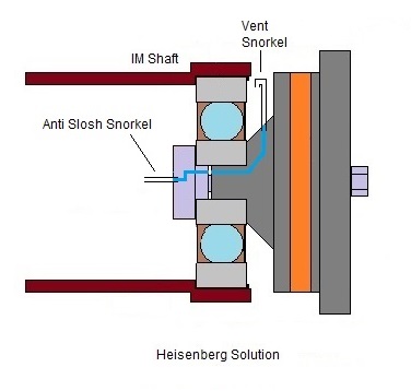
On the vented picture, the vent should go up, and maybe a short section of tubing pressed into the vent hole, going up then bent down like an upside down J to help keep oil from building up in the vent.
Also, realized that the improved bolt has an O-ring that may interfere with my idea. Hopefully it is not too big to interfere.
|
The Heisenberg uncertainty principle. It's kinda like quantum rocket surgery and stuff.
Uncertainty principle - Wikipedia, the free encyclopedia
__________________
Current car
2000 Boxster 2.7l red/black
Previous cars
1973 Opel Manta
1969(?) Fiat 850 Convertible
1979 Lancia Beta Coupe
1981 Alfa Romeo GTV 6
1985 Alfa Romeo Graduate
1985 Porsche 944
1989 Porsche 944
1981 Triumph TR7
1989 (?) Alfa Romeo Milano
1993 Saab 9000
|
|
|
|
|
12-28-2013, 06:26 AM
|
#105
|
|
Registered User
Join Date: Nov 2013
Location: Arizona
Posts: 90
|
Revised drawings
Vent and slosh tubes to help keep vent passage clear of oil
Modified bolt to allow new grease injection directly on to bearing, and provide shoulder to keep push-on cages from popping off.
__________________
It's all bad
|
|
|
|
|
12-28-2013, 06:31 AM
|
#106
|
|
Registered User
Join Date: Nov 2013
Location: Arizona
Posts: 90
|
Quote:
Originally Posted by san rensho
|
That's good. I think I will put that on my You Face Twitter Tube Book.
__________________
It's all bad
|
|
|
|
|
12-30-2013, 07:35 PM
|
#107
|
|
Registered User
Join Date: Apr 2011
Location: DFW
Posts: 713
|
Quote:
Originally Posted by boxster
This issue is driving me crazy. Today I started the car and stayed trying to listed for any noises. I couldnt hear anything from inside the car. then I went near the rear wheels and also couldnt hear anything. then I crawled under the car, and could hear some light ticking sounds, (tick tick tick tick.....) but I have no idea where its coming from exactly, or if it has anything to do with the IMS bearing. the noise is hardly noticeable. but if you crawl under the car and try to block out the exhaust sound, you can hear it. Any ideas what it could be? does it have to be the bearing? or is it normal for a boxer engine perhaps?
|
I had a ticking noise at one point also. Had my bearing done not too long ago and my bearing was fine. That of course is without cracking it open. Turned good though. Usually thats a lifter if I'm not mistaken. Take with a grain of salt.
|
|
|
|
|
12-30-2013, 08:32 PM
|
#108
|
|
Registered User
Join Date: Nov 2013
Location: Arizona
Posts: 90
|
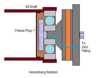
I was just figuring out the minimum and maximum pressure the IM shaft would see if it were sealed with a freeze plug. Using P1/T1 = P2/T2, volume is not a variable. So that would mean that if the bearing is sealed with its own seals, it would see the same changes in pressure over temperature? Venting the shaft would not help? The grease in the sealed bearing will still see the same pressure changes I think.
__________________
It's all bad
|
|
|
|
|
12-30-2013, 10:20 PM
|
#109
|
|
Registered User
Join Date: Sep 2013
Location: Montreal, QC. (currently expat to Shanghai)
Posts: 3,249
|
That is one of many other calculators that we often use for some applications we engineer.
http://www.skf.com/group/knowledge-centre/engineering-tools/skfbearingcalculator.html
Of course Porsche's R&D have designed better formulas, but it could give you a head start selecting a, perhaps?, better bearing than what Porsche initially came us with.
Bearing life, frictional moment, frequencies, viscosity, dynamic bearing load, etc etc...
__________________
______________________________
'97 Boxster base model 2.5L, Guards Red/Tan leather, with a new but old Alpine am/fm radio.
|
|
|
|
|
12-30-2013, 10:22 PM
|
#110
|
|
Registered User
Join Date: Sep 2013
Location: Montreal, QC. (currently expat to Shanghai)
Posts: 3,249
|
Lathes are for cutting  and don't forget to change your oil often. And your bearing will be just fine!
__________________
______________________________
'97 Boxster base model 2.5L, Guards Red/Tan leather, with a new but old Alpine am/fm radio.
|
|
|
|
|
01-01-2014, 12:30 PM
|
#111
|
|
Registered User
Join Date: Nov 2013
Location: Arizona
Posts: 90
|
Even more bad ideas
__________________
It's all bad
Last edited by Walter White; 01-01-2014 at 12:47 PM.
|
|
|
|
|
01-01-2014, 06:47 PM
|
#112
|
|
Engine Surgeon
Join Date: Aug 2008
Location: Cleveland GA USA
Posts: 2,425
|
And just how are you going to machine or EDM that pathway through the flange?
__________________
Jake Raby/www.flat6innovations.com
IMS Solution/ Faultless Tool Inventor
US Patent 8,992,089 &
US Patent 9,416,697
Developer of The IMS Retrofit Procedure- M96/ M97 Specialist
|
|
|
|
|
01-01-2014, 07:22 PM
|
#113
|
|
Registered User
Join Date: Sep 2013
Location: Montreal, QC. (currently expat to Shanghai)
Posts: 3,249
|
It's easy, you vise the part 45degree and you pour 2 drops of 98% H2SO4 in the cavity (sulfuric acid) and wait overnight
Joking aside, that flange will be need to become a quite advanced assembly on it's own if you go this path. I see a 3 pcs (min) flange assembly
__________________
______________________________
'97 Boxster base model 2.5L, Guards Red/Tan leather, with a new but old Alpine am/fm radio.
Last edited by Nine8Six; 01-01-2014 at 07:29 PM.
|
|
|
|
|
01-02-2014, 04:25 AM
|
#114
|
|
Beginner
Join Date: Mar 2013
Location: Houston
Posts: 1,659
|
From a machining perspective, eliminate the 45 leg and drill 2 holes, or if you're heart is set on the 45, drill it from the surface and plug the surface hole. In any event, it appears the path of this hole could be simplified.
|
|
|
|
|
01-02-2014, 07:47 AM
|
#115
|
|
Registered User
Join Date: Nov 2013
Location: Arizona
Posts: 90
|
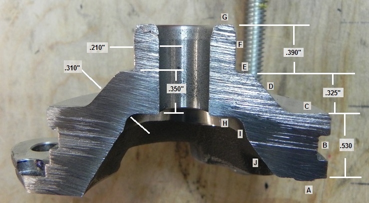
I haven't had time to cut a flange in half to see where I can drill and where I can't, but I hope it will be a simple matter of drill and plug. Like carburetors are made (now I'm dating myself). I hope to simplify the path after I see the profile.
With the path shown above, I think only one plug would be needed. But since there is so little space between the end of the IM shaft and the flange surface, It may be required to recess the snorkel into the flange surface a little. It is very thick in that area and a trough could be cut for the tube without weakening the flange I hope. I think the snorkel will also have to be a high grade rubber tube in order to get the flange installed.
Edit: Oops, correct, make that 2 plugs (good-eye James)
__________________
It's all bad
Last edited by Walter White; 01-02-2014 at 09:25 AM.
|
|
|
|
|
01-02-2014, 10:03 AM
|
#116
|
|
Engine Surgeon
Join Date: Aug 2008
Location: Cleveland GA USA
Posts: 2,425
|
So why don't we just remove the ball bearing completely and not worry about all this?
Yeah, forgot, I already did that.
It'll be interesting to see whatever you come up with.
__________________
Jake Raby/www.flat6innovations.com
IMS Solution/ Faultless Tool Inventor
US Patent 8,992,089 &
US Patent 9,416,697
Developer of The IMS Retrofit Procedure- M96/ M97 Specialist
|
|
|
|
|
01-02-2014, 03:41 PM
|
#117
|
|
Registered User
Join Date: Nov 2013
Location: Arizona
Posts: 90
|
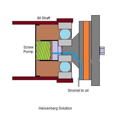
Single row IMSB flange
__________________
It's all bad
|
|
|
|
|
01-02-2014, 05:03 PM
|
#118
|
|
Beginner
Join Date: Mar 2013
Location: Houston
Posts: 1,659
|
So is the thought to run a pump inside the IMS shaft using the rotation motion of the shaft and the stationary bearing retaining stud? The oil then exits through an open bearing into the crankcase? I'm not sure what type of pump would lift the oil, but this concept is intriguing. Maybe some type of modified stator vane pump? First pumps air to create a vacuum and lift the oil, and then can handle oil as well? That would eliminate any new moving parts, make the stator and vanes part of a new stud and IMS tube closeout? Neat idea. Lots of technical challenges come to mind. Keep going and have fun!
|
|
|
|
|
01-02-2014, 05:34 PM
|
#119
|
|
Registered User
Join Date: Nov 2013
Location: Arizona
Posts: 90
|
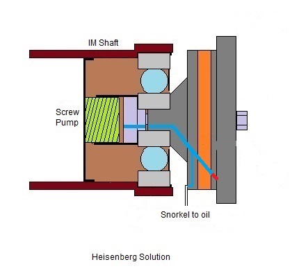
I'm looking at pumping the oil. It would be nice if it could be done. As I see it, the oil only has to be lifted about an inch. There are several types of pumps that may be viable. But yes I have considered the stator type too. Plan B is to be able to pump grease into the bearing. The biggest question now is can a tube fit down into the sump from the flange. Always looking for help. That's why I post the pics.
__________________
It's all bad
Last edited by Walter White; 01-02-2014 at 05:36 PM.
|
|
|
|
|
01-02-2014, 05:39 PM
|
#120
|
|
Engine Surgeon
Join Date: Aug 2008
Location: Cleveland GA USA
Posts: 2,425
|
Always consider the windage that your "fix" may create. Foamy oil has no film strength.
Nothing like solving one problem only to create another thats 10X more critical for the rest of the engine.
__________________
Jake Raby/www.flat6innovations.com
IMS Solution/ Faultless Tool Inventor
US Patent 8,992,089 &
US Patent 9,416,697
Developer of The IMS Retrofit Procedure- M96/ M97 Specialist
|
|
|
|
 Posting Rules
|
You may not post new threads
You may not post replies
You may not post attachments
You may not edit your posts
HTML code is On
|
|
|
All times are GMT -8. The time now is 09:12 PM.
| |


 Mean Motor Scooter
 Linear Mode


