Go Back   986 Forum - The Community for Porsche Boxster & Cayman Owners > Porsche Boxster & Cayman Forums > Boxster General Discussions

Post Reply
 
LinkBack Thread Tools Display Modes
Old 12-04-2016, 02:57 PM   #1
Registered User
 
Join Date: Dec 2014
Location: Pasadena
Posts: 261
Vacuum line clarification

So, I'm still fighting a p1128 after about 500 mi and doesn't allow SAI to go ready. While hunting down Vaccum line pics I came across this. My 02-S only has the one vacuum line going into bank 1 side resonance flap coupler. Bank 2 does not have the vac hookup. Am I suppose to have 2 hookups to the resonance tube? Or is this another earlier year boxster? The area is L/B. This vacuum Sh#ts Driving me nuts.


Last edited by Lapister; 10-06-2017 at 02:22 PM.
Lapister is offline   Reply With Quote
Old 12-04-2016, 06:26 PM   #2
Ben-Auto-Design
 
Ben006's Avatar
 
Join Date: Oct 2014
Location: French Riviera
Posts: 827
You're getting P1128 alone? no P1130?

Can be a lot of things.
If it only affects bank 1, I'll look into dirty injectors.
__________________
ASE certified Automotive Master Technician.
Porsche Tech in France.
www.benautodesign.fr
Ben-Auto-Design : Performance parts for 9X6 / 9X7
1982 928 S Euro
Ben006 is offline   Reply With Quote
Old 12-04-2016, 07:04 PM   #3
Motorist & Coffee Drinker
 
78F350's Avatar
 
Join Date: Jul 2014
Location: Oklahoma
Posts: 3,849
Garage
In regard to the vacuum connections, here's that diagram, created with actual parts from a scrapped 2001 2.7L.
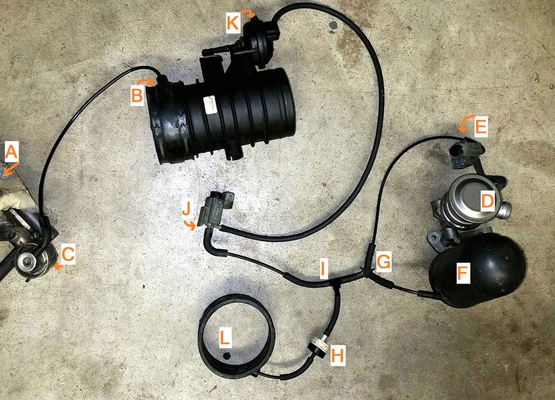
Notes:
-This picture shows what connections have to be made, the actual order of connections to the Y fittings (I) and (G) are not critical.
-The Tiptronic cars will have a 4-way connection at (I) or (G) with a line running to a changeover valve on the transmission.

It looks like a mess of tubes and parts, but in function it is fairly simple.
This shows 3 vacuum powered components: SAI, Resonance Flapper, and Fuel Pressure Regulator. Brake booster vacuum system is not shown.
SAI: Vacuum source -> electric change-over valve (E) -> change-over valve (D).
Resonance Flapper: Vacuum source -> electric change-over valve (J) -> vacuum unit (K).
Fuel Pressure Regulator: Vacuum source (B) -> Pressure regulator (C) -> injector valves (A).

Rubber sleeves (L) and (B) are the source of vacuum from the intake. (H) is a check valve. (F) is the vacuum reservoir.
__________________
I am not an attorney, mechanic, or member of the clergy. Following any advice given in my posts is done at your own peril.
78F350 is online now   Reply With Quote
Old 12-04-2016, 07:24 PM   #4
Registered User
 
Join Date: Dec 2014
Location: Pasadena
Posts: 261
So, I guess my real question is do all boxsters regardless of years have the Fuel pressure reg operating off the resonance tube coupler via vacuum. My quick look didn't seem to notice a pastiche vacuum pipe going to the driver side resonance coupler. Item B

Last edited by Lapister; 12-04-2016 at 07:26 PM.
Lapister is offline   Reply With Quote
Old 12-04-2016, 07:30 PM   #5
Motorist & Coffee Drinker
 
78F350's Avatar
 
Join Date: Jul 2014
Location: Oklahoma
Posts: 3,849
Garage
Look at your fuel pressure regulator (C) front left side of the engine and see where the vacuum line goes. It can be in a different location on the intake, but it does require vacuum.
__________________
I am not an attorney, mechanic, or member of the clergy. Following any advice given in my posts is done at your own peril.
78F350 is online now   Reply With Quote
Old 12-05-2016, 04:58 AM   #6
Project Addicted
 
jcslocum's Avatar
 
Join Date: Aug 2015
Location: Eastern Shore, MD
Posts: 623
How about a smoke test???

1128 is likely a vacuum leak on the one side.

Do you have a Durametric setup?
__________________
______
Jon
1966 912, 1976 911
1986 944, 2000 Boxster
jcslocum is offline   Reply With Quote
Old 12-05-2016, 09:00 AM   #7
Registered User
 
Join Date: May 2014
Location: S.California
Posts: 2,029
Smoke test is a good idea. Where is the best place to connect? I used an AOS hose but the system has a huge capacity for smoke ! It would be better to use adapters to connect to smaller hoses? The problem is the smoke will eventually cool and condense in a large space ,so it is better to do this with a warm engine.
Gelbster is offline   Reply With Quote
Old 12-05-2016, 09:12 AM   #8
Registered User
 
Join Date: Dec 2014
Location: Pasadena
Posts: 261
I don't have a Durametric and I just want to get it past Commiefornia emissions. It probably is just a minor vac leak and being a p1128 probably on passenger bank. Have checked vac lines to Resonance flap and SAI. The only area I can't see is FP reg cause it's buried under the 987 Airbox but if it were the area of leak I would think it would throw a p1130 since its on driver side.
Lapister is offline   Reply With Quote
Old 12-05-2016, 09:18 AM   #9
Registered User
 
Join Date: May 2014
Location: S.California
Posts: 2,029
Suggest you find an Indie with a big smoke machine and test. It should not take more than 20 minutes to do the Test.
What happened with all your other SAI issues and Smog Test woes ?

Last edited by Gelbster; 12-05-2016 at 09:22 AM.
Gelbster is offline   Reply With Quote
Old 12-05-2016, 10:20 AM   #10
Registered User
 
Join Date: Dec 2014
Location: Pasadena
Posts: 261
My pockets aren't too deep but I have short arms. This is strange as I've looked at a lot of pics of where the FPR should be usually at the end of the fuel rail and I don't have one. I wanted to check for vac line there on driver side front as most pics reflect and I don't see it. I do know that this 02 model-S does not have a replaceable fuel filter either. Supposedly has a lifetime unit. Does anyone have a MY02 that can confirm? Going nuts!
Could it be integrated into the fuel pump? I do not see it on either side fuel rail.

I just did a little more digging and found that infact MY02-04 has a closed fuel system and its like
Y the FPR is integrated into the FP. Oh, the joys and that only a Dealer software can check these. The bank 1 fuel rail does have the schrader valve though for a pressure check. I will see how that comes out.

Last edited by Lapister; 12-05-2016 at 10:49 AM.
Lapister is offline   Reply With Quote
Old 01-15-2018, 09:32 AM   #11
Registered User
 
Join Date: Jul 2017
Location: Tucson AZ
Posts: 536
Quote:
Originally Posted by 78F350 View Post
In regard to the vacuum connections, here's that diagram, created with actual parts from a scrapped 2001 2.7L.

Notes:
-This picture shows what connections have to be made, the actual order of connections to the Y fittings (I) and (G) are not critical.
-The Tiptronic cars will have a 4-way connection at (I) or (G) with a line running to a changeover valve on the transmission.

It looks like a mess of tubes and parts, but in function it is fairly simple.
This shows 3 vacuum powered components: SAI, Resonance Flapper, and Fuel Pressure Regulator. Brake booster vacuum system is not shown.
SAI: Vacuum source -> electric change-over valve (E) -> change-over valve (D).
Resonance Flapper: Vacuum source -> electric change-over valve (J) -> vacuum unit (K).
Fuel Pressure Regulator: Vacuum source (B) -> Pressure regulator (C) -> injector valves (A).

Rubber sleeves (L) and (B) are the source of vacuum from the intake. (H) is a check valve. (F) is the vacuum reservoir.
I know this is a kinda old post.Thank you for posting it. It is the clearest I've seen

If you're ever in Tucson, message me, I'll have a six pack with your name on it.
__________________
2001 Boxster
2007 Toyota Highlander
2003 New Beetle Convertible, Turbo, Tip 6 speed
Brian in Tucson is offline   Reply With Quote
Old 01-15-2018, 09:44 PM   #12
Registered User
 
Join Date: Sep 2017
Location: MALIBU
Posts: 166
I had a similar vacuum leak and SAI that would not reset.

Trying to get the 986 smogged in CA.


I had multiple vacuum leaks.

My vacuum reservoir was leaking. I put a vacuum hand pump and gauge on it with the reservoir in place and used long needle nose pliers to get the hose off and connect a test hose directly to the canister. It would not hold vacuum, but the replacement reservoir would hold vacuum.

New reservoir was like $22.

[you have to take the alternator out to reach the reservoir for R&R. I just put the second reservoir in the corner of the engine compartment and left the old one in ther unhooked from the vacuum system.]

I also had the at "L" not in the hole in the rubber part. I used a brass barbed fitting in the rubber manifold and high temp silicon tubing to connect the check valve.

I replace every bit of rubber hose I could with 3mm silicon hose.

I then inserted a vacuum gauge in the system with a "T" fitting. The manual says you should get from 12 to 19 inches of vacuum at idle. I had about 17.

Then all the "MONITORS" went away. If you have a Durametric you can see if the monitor pass or fail.

Be happy to answer any questions or PM me.
__________________
2003Boxster
1973 Carreras RS tribute
2000 Saab Aero wagon stick
1990 Chevrolet pu pre runner

Last edited by boxfix; 01-16-2018 at 07:58 AM.
boxfix is offline   Reply With Quote
Old 01-28-2018, 08:54 PM   #13
Certified Boxster Addict
 
Join Date: Nov 2010
Location: Los Angeles
Posts: 7,669
Quote:
Originally Posted by 78F350 View Post
Thank you. Thank you. Thank you.

I needed this today to figure where the vacuum lines from the throttle body sleeves attach (H and C).
__________________
1999 996 C2 - sold - bought back - sold for more
1997 Spec Boxster BSR #254
1979 911 SC
POC Licensed DE/TT Instructor
thstone is offline   Reply With Quote
Old 01-29-2018, 06:31 AM   #14
Registered User
 
Join Date: Feb 2014
Location: St. Louis, MO
Posts: 41
Were you able to see data from the O2 sensors via OBDII?

Pretty certain i could watch the cycling of the O2 sensors on my LS1 car via OBD2 data software, if one of the sensors isn't registering voltage changes, it's likely bad and as a result adjusting fuel towards that bank...which can obviously cause a lean or rich condition depending on the failure mode.
flynavyj is offline   Reply With Quote
Old 11-19-2018, 12:35 PM   #15
Registered User
 
Pigsypo's Avatar
 
Join Date: Nov 2018
Location: Central valley
Posts: 22
great diagram and i'll refer to it to fix 2003 boxster that i'm working on right now.

The secondary injection line is broken into pieces and rubber connectors are cracked. I'm working on replacing those. what's the part number for the rubber hose for part E in the picture?
Pigsypo is offline   Reply With Quote
Old 11-19-2018, 12:41 PM   #16
Registered User
 
Join Date: May 2014
Location: S.California
Posts: 2,029
Suggest you search for other posts where the stock parts were replaced by high quality silicone hose and brass barbed fittings. That combo will never fail. IIRC the hose is 3mm but verify. The silicone is very stretchy.

Gelbster is offline   Reply With Quote
Post Reply


Posting Rules
You may not post new threads
You may not post replies
You may not post attachments
You may not edit your posts

BB code is On
Smilies are On
[IMG] code is On
HTML code is On
Trackbacks are On
Pingbacks are On
Refbacks are On


All times are GMT -8. The time now is 05:37 PM.


Powered by vBulletin® Version 3.8.7
Copyright ©2000 - 2025, vBulletin Solutions, Inc.
Content Relevant URLs by vBSEO 3.6.0
Copyright 2024 Pelican Parts, LLC - Posts may be archived for display on the Pelican Parts Website -    DMCA Registered Agent Contact Page