Go Back   986 Forum - The Community for Porsche Boxster & Cayman Owners > Porsche Boxster & Cayman Forums > DIY Project Guides

Post Reply
 
LinkBack Thread Tools Display Modes
Old 01-05-2015, 03:34 PM   #101
Registered User
 
flaps10's Avatar
 
Join Date: Jul 2014
Location: Tacoma
Posts: 430
Markus,
No worries. Post away.

Jamesp,
There are some great pointers in your post. If I may point out something in the picture that you posted, it looks like the edge of that ring groove is pretty hammered. I only noticed it because I saw a post elsewhere and the person managed to chip off a pretty good chunk of piston clear up to the oil ring groove.

I would seem that lining up the circlip insertion tool is super important, and that possibly some people are confusing a swift palm against the knob of the insertion tool with the need for extreme force.

I managed to install the circlips on my pistons 1-3 the other day without any special tooling, but I think I'll remove them once my insertion tool shows up and get a really good idea for what it feels like. Needless to say, the whole bank 4-5 thing is causing me to ponder things. I'm hoping Jake's new tool hits the market soon.

Update:
Not that anyone is sitting on the edge of their seats waiting for me to update this thread, but it has taken a turn or two recently.

The good news is that I'm on my way back together. The bad news is that everything from the bearing carrier "out" is going to be restricted to fresh seals. For now.

My reasoning is as follows. As just mentioned by user jamesp, I have a snapped off oil ring. For those not familiar, the oil ring is in three pieces. There is a heavily perforated T shape piece that goes in the groove and there are very thin steel rings that go above and below the perforated piece. Using a conventional ring compressor it would be very easy to get one of those super thin pieces out of shape and viola, you get a bore scratch just like I have. And a missing piece of ring that surely did some great work on its way to the filter. For the record, one of my recent purchases was an ARP tapered sleeve ring compressor which should go a long ways towards reducing the chances of buggering up another oil ring.

I did some pondering on the ring situation. In a normal engine (which the M96 is decidedly not) you would bore the cylinders to the next size up and then buy new pistons and rings to go with them. There are no off the shelf, next size up pistons for the M96. That sort of supports the idea that this is a throw away motor in Porsche's eyes and will eventually whack that line they love to publish in their ads (70% of all porsches ever made are still on the road). In the future that may only be true if you count the number of 986/996 cars with an LS or Subaru engine.

But I digress.

I was hoping to get this back together perhaps not "on the cheap", but at least not have to hang my head in shame as to what I put back inside. What I wanted to do was get fresh rings, do a bore hone to give them a new surface and hope that my scratch was diminished.

I took the case halves back to my local engine building shop, which is well known for doing V8 hot rods but he down plays any Porsche work he's done (he knows more than he lets on). His assistant pointed out my sleeve material and he held up his hands and said he would only be making my problem worse to even hone them out.

For anyone who is curious what is meant by that, removing material from the bores will also remove the high silicone content of the bore surface, leaving you with some dead soft aluminum to rub up against your steel rings. How much can you remove and still be safe? I don't know, but I'm glad that the shop I was in was honest enough to say he didn't know the answer either.

You can of course get the case halves resleeved and use stock size pistons and rings. Look up any shop that does sleeving (probably with iron sleeves), price stock pistons, and stock rings then do the math and you'll discover what I did: That the LN "Nickies" are the cheapest deal on earth by at least $1000. For a total throw down of about $4600 I can have my choice of 3.2, 3.4 or 3.6 liter with Nickies sleeves and JE pistons and rings.

What was not clear to me from the LN web page was whether they were selling case halves with the sleeves in them for that price or if it was exchange, or ship 'em in or what. I had to talk to someone at LN today anyway about my recent order and if anyone is curious the prices quoted on their web page are for you to send in your case halves for the work to be done. They have no stock of cases ready to rock. He told me current turn around is around 8-10 weeks.

Now I know that part at least.

So here is the part where I hang my head in shame. I don't have $4600 right now, plus the $1500-1600 for a decent set of non throw away connecting rods and another $1300+ for LN to pin my IMS and install a three row ceramic bearing (dammit, just realized I forgot to ask if they still do that).

I can set aside that kind of money but it will be probably six months or so. Again, this car is a hobby - although I'm starting to think that hookers and blow are cheaper. Even though it's a hobby I still want to drive the damn thing.

My new plan is to go with my rebuilt lower end and reuse the case halves, pistons and rings except for the oil ring that is busted off. I can't even believe I just typed that, but there it is. It just seems like trying to re-ring the thing is throwing good money (stock rings are about $250/hole) after bad (out of round bores, my scratch, etc).

My reasoning continues as follows. First, my car ran perfectly when I pulled into my garage to start this project. It didn't burn or leak any unreasonable amount of oil. The car I will pull back out of my driveway will be much better than the one I pulled in - with no metal floating around inside. Oh, and by the way I'm installing the LN filter assembly and magnetic plug.

Next, I'm going to know a heck of a lot more on my second engine build than I will on this first one. I will be able to go to one of Jake's classes and have a heck of a lot higher chance of absorbing more information because I will have held all these parts in my hands already. And after that I'll be ready to have some case halves done and ready to go.

I've got the full support of my woman and the place to do all this.

With that out of the way, here is a quick shot of my bearing carrier on the bench.


Case half for bank 1-3 is ready to go. The bad news from LN earlier today was that I won't see that tapered sleeve ring compressor until near the end of the month.

I am going to break down and source an engine stand, to answer another question posted earlier.

flaps10 is offline   Reply With Quote
Old 01-06-2015, 01:36 PM   #102
Registered User
 
Join Date: Apr 2008
Location: pa
Posts: 32
There is a post on Rennlist by speedrII who did a similar approach of reusing rings etc on a 996 and it worked .Not sure if you have seen it .

Dave
dcdrechsel is offline   Reply With Quote
Old 01-06-2015, 02:52 PM   #103
Registered User
 
BYprodriver's Avatar
 
Join Date: Oct 2008
Location: O.C. CA
Posts: 3,709
Garage
I have some good used piston rings for 3.2L I can send you.
__________________
OE engine rebuilt,3.6 litre LN Engineering billet sleeves,triple row IMSB,LN rods. Deep sump oil pan with DT40 oil.
BYprodriver is offline   Reply With Quote
Old 02-16-2015, 04:17 AM   #104
Registered User
 
Join Date: Jun 2014
Location: LB, Germany
Posts: 1,456
Hello flaps10,

in germany we do have specialized companies that can do Lokasil and Nikasil coatings on used/worn cylinders. Maybe you should do a research if some companies in the US offer that too.

Steel sleeves in aluminium blocks have some big disadvantages, because of different expansion of the the different metals at higher temperatures.

Regards
Markus
Smallblock454 is offline   Reply With Quote
Old 02-18-2015, 12:50 PM   #105
Registered User
 
flaps10's Avatar
 
Join Date: Jul 2014
Location: Tacoma
Posts: 430
Well I'm finally on my way back together. I had been waiting for my order from LN Engineering which included the tapered sleeve ring compressor. They had been on back order for a few weeks. When it arrived I was out of excuses.

Well, almost out. Knowing that one of the modes of failure for the M96 is when one of the sprockets on the IMS slips, causing an instant timing deviation and possible catastrophic failure (if you consider valves impacting pistons to be catastrophic anyway), I wanted to do something to mitigate the potential.

I had stumbled across this video while surfing the issue:
https://www.youtube.com/watch?v=XP6GwqLvD7Q

So I did it at home. I don't have a milling machine with DRO, but I do have a drill press and a half way decent set up for drilling holes in metal stuff:


Okay now I'm out of excuses.

I decided to install the IMS bearing into the shaft before putting the shaft in. No reason not to, and it sure is easier to reach.

I'm going to be a guinea pig for the EPS roller bearing. The bearing went in the freezer for what turned out to be a couple of days and my intermediate shaft went in the oven for a while to gain as much elbow room as possible. (Warning: did cause a funny smell I had to explain to my woman). Coming out of the oven the shaft went vertical into my vise so the entire load of me 'encouraging' the bearing into place didn't transmit through anything but the gear I pressed it in to. I used their install tool and a plastic dead blow hammer to get the bearing to sit solid in the pocket.


In.

Other things about the EPS bearing. The current price on the vertex site is $439, and it turns out that includes the kit to do the oil feed. The kit consists of a tapered punch and the revised oil pump drive shaft. Having seen the images of the groove in the oil pump drive I was surprised to find out the groove is quite small (0.093" wide and 0.005" deep by my measure). The punch? Not a fan. The instructions tell you to punch a 1-3mm hole in the back of the drive shaft hole. That's a huge range. Being as my shaft was still on my bench, drilling a 0.078" hole and blowing the shaft out with compressed air seemed like a better option.


I fit the bearing carrier to the crankcase half for cylinders 1-3. There are two bolts which exist to hold the bearing carrier to this case half but they are both at the same end of the engine (the rear in our boxster case). Porsche special tool #blah, blah lets you use a cylinder head bolt to secure the other end.


As you can see I have two such special tools which do double duty as 1/2" drive sockets. Those head bolts are just tight enough to keep the bearing carrier from having any slop and are not in any danger of marking up the mating surface common to the cylinder head.


The two bolts dedicated to holding the carrier to the case will eventually be joined by a really long one from the opposite case half. The manual I have tells me not to bring those bolts to final torque until the case halves are bolted together. So just like the head bolts being used to hold the carrier to the case, I have them just snug enough to do the job.

You can also see pistons 1-3 in place in these pictures. Thanks to the tapered sleeve ring compresser, getting them in was stupid easy and actually a little fun.

The crank pulley is on in order to facilitate rotating the crank shaft to the various positions required to install the pistons.

The basic process it rotate the engine so the rod journal is the furthest away from the cylinder head surface. You take a piston with connecting rod attached, remove the bearing cap and feed it into your ring compressor (lots of clean oil on everything). Then you feed the assembly into the engine from the cylinder head side. It found it quite easy to reach into the bearing carrier and gently guide the rough scratchy end of the connecting rod to meet the crankshaft.

You've already triple checked the piston orientation (cylinder number, "up", etc) and now it's time to get super careful with the connecting rod caps. First off, orientation which I made simple by running a random line with a fat sharpie across the joint of the rod and cap before taking it apart. The pen mark also makes it very easy to see side to side mismatch.

The super careful part is as follows. These (stock) rods are of the "fractured" variety. They literally forge the connecting rod and do all the machining, and the break it in a predetermined spot. The fractured spot has a granulated structure to it, and the idea is that it takes place of any dowel pins, etc. and maintains precise location.

You can't just sock your rod bolts down and assume that the alignment is dead perfect both top and bottom. You need lots of light and get your face in there and make sure. I gently installed the rod bolts while holding the cap in place, just finger tight. Then I pulled out the pin holding the crank pulley and rotated the engine back and forth to check to make sure the rod caps were going on absolutely perfectly and snugged the bolts back and forth. I had to back up a few times over all but it wasn't really difficult.

Once happy I finished torquing them down.

Next I spent an hour going over the case half for cylinders 4-6, getting rid of any remaining sealant and then blowing the hole thing out with my air compressor.

When I get home today my latest pelican order will be on the porch which contains Drei Bond and head gaskets.
flaps10 is offline   Reply With Quote
Old 02-18-2015, 03:12 PM   #106
Registered User
 
jaykay's Avatar
 
Join Date: Sep 2009
Location: toronto
Posts: 2,668
Very interesting....what material are you using to ensure that the screw never backs out? Is there an issue with balancing such that another screw is required at 180 degrees ...and some grinding after balancing this component?

I am very curious about this roller bearing; I have never heard anything about it. Is all thrust on the IMS resolved at the other end such that rollers will survive? No wishes to start a bearing feud ....just straight technical questions.

Cheers
__________________
986 00S

Last edited by jaykay; 02-18-2015 at 03:21 PM.
jaykay is offline   Reply With Quote
Old 02-18-2015, 03:42 PM   #107
Registered User
 
Join Date: May 2014
Location: S.California
Posts: 2,027
Flaps
Well done, & thanks for sharing.
I am just a few steps ahead of you in the process.I make far too many mistakes to share with everyone.It would be humiliating ;-).

A few hints for others.
1."Jugs" - Wiseco and others sell these(Jegs/Summit etc) 93mm. Use lots of oil.

2. I splurged on ARP bolts for the bearing carrier,rods and head. The OEM bolts were about the same price and imho inadequate. I am very impressed with ARP's material science/engineering. Their Marketing is questionable. I had to buy items intended for a 996 -they weren't sure if it would fit a 3.2l Boxster ! Now they know -from me!
The expert I found is:
Alex Crostic - Specialty Products Coordinator
Automotive Racing Products, Inc. (ARP)
Web: ARP | The Official Web Site
When you compare Porsche fasteners with ARP it is like a comparison between hardware store general purpose made-in-china. Sad but true.

3. John Edwards - Costa Mesa R&D Brilliant guy . I use him. He is a wonderful curmudgeon. Doesn't suffer fools. So don't expect Engineering/Machining 101 from him over the phone.He literally wrote the book on engine machining for Sunnen. You will be talking to a god.
Sunnen's Complete Cylinder Head and Engine Rebuilding Handbook: John G. Edwards: Amazon.com: Books
He has lots of relevant videos on Porsche, Subaru, Fiat. If you want to impress him - talk to him about Zastava gearboxes for the 128. Pure porn for him! And sadly for me too .

hope this helps/amuses.Happy Boxster repairing.

Last edited by Gelbster; 11-05-2015 at 06:20 PM.
Gelbster is offline   Reply With Quote
Old 02-18-2015, 04:09 PM   #108
Registered User
 
Join Date: May 2014
Location: S.California
Posts: 2,027
"I'm going to be a guinea pig for the EPS roller bearing." + DOF
Woops you do not have the 'real' DOF - if by that you mean a direct feed from the cam cover port. Big difference compared to the oil-pump drive-shaft hack ,er modification.
Flaps you are performing a great service to the M96 community.Thank you. I applaud your potential sacrifice of an expensively repaired M96 - just to prove the futility (I sincerely hope I am wrong!) of defying the IMSB gods and gurus.

We have had a few inconclusive debates about roller vs. ball bearing. I prefer field experiments - particularly with someone elses engine-yours !

My pure and unsubstantiated WAG is that the oil feed to the bearing will 'save' the roller bearing .That is a gratuitous & uninteresting assertion. The significant part is WHY? In theory( unsubstantiated theory!) ,the new oil supply will cool the bearing sufficiently and you will use oil with enough thermal shear resistance(& change frequently) to offset the clumsy inherent characteristics of the roller bearing. You will drive it gently enough to never snap the oil pump drive and you will never 'tax' the engine.
After a few thousand miles, you will declare a triumph for the roller bearing IMSB and have many devoted followers. You may even get an email congratulation from Feelyx(they guy who championed the roller bearing idea long ago and on a different Forum).
Now if you used a real DOF from the cam cover - that would be fascinating ! But then you wouldn't need the roller - a deep grove ball bearing would be adequate?Oh no , another IMSB thread!
You may find some interst/amusement here:
http://rennlist.com/forums/boxster-and-boxster-s-986-forum/851476-broke-piston-with-baum-circlip-tool-help-please.html

Sincere thanks for your story and good luck !

Last edited by Gelbster; 02-19-2015 at 07:43 AM.
Gelbster is offline   Reply With Quote
Old 02-18-2015, 07:23 PM   #109
Registered User
 
flaps10's Avatar
 
Join Date: Jul 2014
Location: Tacoma
Posts: 430
Jaykay,
If you watch the video in the link i posted you'll see how the set screw is retained. The video was produced by the person gelbster mentions - John Edwards of Costa Mesa R&D. Basically by careful use of the tapered tap, you can cause the screw to basically run aground against the uncut portion of the threads at the bottom of the hole at the exact same time the screw goes below flush on the outside.

He uses some high temp thread locking goo. I used JB Weld. That screw is not going anywhere. I considered running another screw at 180 degrees to balance the first, but the weight of a set screw is going to be very close to the weight of the materiel removed during drill and tap. Given the difference between those two weights relative to the mass of the shaft , I'm not going to lose any sleep over balancing.

Gelbster,
I won't ever declare victory, and certainly not after a few thousand miles. The only time my vehicles are driven carefully is while waiting for temps to come up. What i will do is share what i learn along the way. This has been a very educational process.

I too am running the ARP rod bolts. I got the bearing carrier bolts but they came with the instruction to align bore the carrier. That's not happening this time around, so I'm sitting on those bolts until next time.
flaps10 is offline   Reply With Quote
Old 02-23-2015, 03:31 PM   #110
Registered User
 
flaps10's Avatar
 
Join Date: Jul 2014
Location: Tacoma
Posts: 430
As I type I'm reminded of the old Monty Python segue: "And now for something completely different".

This next series of steps with the M96 is really the only part which has caused me to stress out, because I've never done anything like it. I've seen the apt reference that installing pistons 4-6 is akin to building a ship in a bottle.

I needed a lot of practice. And practice I did.

Getting the wrist pin retaining clips in is challenging enough just sitting on your wood bench with good light. If it doesn't seat perfectly there is a very high probability that it will jump out during the first engine run and sod things up for good.

So I got a bunch of practice with my tools. After marking the tool for depth at each cylinder location I started installing piston #6 (the furthest one) and went through the process.

In my first 10 attempts at inserting the the retaining clip for cylinder #6 I got it properly seated 1 time. That was not anything like a good enough average to bother with breaking out the Drei Bond. So I kept at it, fine tuning my technique, polishing the segment of the tool which has to mate up perfectly with the piston before "firing" the wrist pin. Finally I began getting it consistently and now I can tell just by the feeling through my hands that it is seating property.

Next, I rotated the case half so I couldn't see inside because that is cheating and I wouldn't be able to do that with the case halves together. Here is where my earlier practice paid off because I was getting pretty good at setting up the wrist pin clips in the tool just using my fingers.

Cylinders 5 and 4 were much easier. If anything the tool runs a little sloppier the more it comes out of the case and it would be easy to mess up if you get complacent.

Next I cleaned both case halve joining surface with acetone, then got out the Drei Bond and made a bead, then had my youngest son help me by guiding the timing chain and connecting rods while I lowered the case half onto the other one.

I hurriedly got screws in all the locations and then used my air ratchet wrench to bring the case halves just snug. Then I whipped out the torque wrench and got all the case half screws to spec, in the order the book says. I'm not ashamed to admit that I use a sharpie pen to write the torque sequence directly on the engine. When I'm done an acetone rag destroys any evidence that I suffer from CRS.


Now I have to position the engine so that the cylinder bores are upright and I can rotate the crankshaft. Then we'll see if I really practiced enough.
flaps10 is offline   Reply With Quote
Old 02-23-2015, 04:07 PM   #111
Registered User
 
Join Date: May 2014
Location: S.California
Posts: 2,027
Flaps,
You are still at a nerve wracking stage -are those circlips correctly seated? How did you inspect them?
In my "broke the piston" thread elsewhere I describe a few tricks like a wood V-block to cradle the piston, using an illuminated endoscope and big-screen laptop to verify placement of the circlips inside the engine.I also made the "Logray hook" to tug at the circlips to try to pull them out after inserting them.Yup, # 4 came out!!!!Fortunately I retrieved it.
After that I removed the 'hook end' on the 3 difficult circlips. That eliminated the micro alignment requirement. It is all in that thread. I do not recommend anything I did because I have no proof it works yet ! The fact that it rotates by hand 'smooth as buttah' to quote our mentor -is irrelevant .It would do that with no circlips at all!
It is interesting to see the video of how John Edwards inserts circlips in the Subaru H6.Totally different to Baum. Jake's new tool is easier because it eliminates the slapping/banging nonsense.
Thanks for explaining what you have done - it will help others who follow.
Gelbster is offline   Reply With Quote
Old 02-25-2015, 08:54 PM   #112
Registered User
 
flaps10's Avatar
 
Join Date: Jul 2014
Location: Tacoma
Posts: 430
So what do you do when you're stuck at home, borderline delusional with fever and chills (besides buying a 14 year old sports car without a thorough pre buy - so last summer)?

Why, you install piston 4-6 of course!

I wish i could say i was kidding. I also wish i could say could say i was successful.

Piston #6 had me the most nervous. It went off without a hitch. My insertion tool marks dropped into place just the way i practiced and i knew instantly that the snap ring landed correctly. I almost didn't bother to create the flashlight on mirror tool, but that would have been a really stupid move. It really did go in exactly as desired.

With piston #5 it started out smoothly enough. But where you should verify the tool to your marks and not 95% sure, i sent the clip home and this time it did not sound right. Flashlight on mirror tool confirmed that the clip is sitting perfectly on the outside of the snap ring groove.

Didn't want to risk shooting the wrist pin clip into the crank case, so i got real careful. Did some pondering and had an idea to save the day. I spent $11.35 at my local home box store and brought home the materials to create the required tool.

I'll post up a diagram and some pictures tomorrow.
flaps10 is offline   Reply With Quote
Old 03-01-2015, 02:59 PM   #113
Registered User
 
flaps10's Avatar
 
Join Date: Jul 2014
Location: Tacoma
Posts: 430
The tool i devised consists of a piece of 1/4-20 all thread, an acorn nut, a piece of 1/2" copper pipe (which is about 5/8 OD), a piece of fuel hose and a few more 1/4-20 nuts.

I first did a mock up as follows


Basically this is a Chinese finger puzzle, or viewed another way out is similar to the way some of you extract your spark plug tubes. Picture a small diameter boat drain plug on an extension.

I had hoped to find a socket which would slip inside the copper pipe. I would have sacrificed a cheap socket for the cause. That size combination didn't materialize, so i ended up bonding a nut in the end of the tube using JB Weld. In addition, the rubber piece on the finished product is around 2" long. As shown it wouldn't get past the deep chamfer in the wrist pin.

The diameter of the copper is required to retain the wrist pin when it comes out of the bore.

It worked perfectly.


Above picture taken down the cylinder bore after the wrist pin was extracted. This shows how the clip is kept from dropping inside the engine.


Extracted.

Half an hour later i was done installing the last of my pistons.

Huge relief to have that behind me.
flaps10 is offline   Reply With Quote
Old 03-01-2015, 03:26 PM   #114
Registered User
 
Join Date: May 2014
Location: S.California
Posts: 2,027
This clever device should be indexed and bookmarked as the" FLAPS circlip retrieval tool" Logray also has one on Renntech but this is a safer solution.
For those who don't 'get' the significance of his invention there is one question -
1.If you fumble the extraction of a mis-fired piston circlip -and it drops inside the engine, how much time and cost is involved in finding it and safely removing it?
Far worse is if your inspection system is inadequate and you incorrectly conclude the circlip is perfectly installed. Imagine the carnage when it dislodges and the wrist pin flops around.....

I had this exact misfire problem and I very gingerly removed the circlip with the Logray hook - a nerve wracking exercise in co-ordination and luck. It worked only because the clip did not rotate even a few degrees and slide off into the bowels of the newly rebuilt engine!
This is a great diy tool. Thanks for sharing Flaps!
Gelbster is offline   Reply With Quote
Old 03-24-2015, 10:57 AM   #115
Registered User
 
flaps10's Avatar
 
Join Date: Jul 2014
Location: Tacoma
Posts: 430
Update:


All the tough stuff is behind me. From here it is bolting on accessories, and getting it pushed back into the gaping hole.

Not a whole lot to report on the assembly of cams, timing etc. It's all been said before or posted in a way I can't match. The 986fix videos came in handy a time or two.
flaps10 is offline   Reply With Quote
Old 03-24-2015, 12:09 PM   #116
Registered User
 
Join Date: May 2014
Location: S.California
Posts: 2,027
Flaps,
Tough stuff behind you ?
Let us know how you do with the vacuum hoses and wiring harness. It is a bewildering puzzle. I tried using labels but they came off ! I was really depending on them. Making the connections is easy. The routing and sequence is baffling.
Worse it is very difficult to photograph well. Wayne's photos are a great help.
Share your success?
Gelbster is offline   Reply With Quote
Old 03-26-2015, 09:36 PM   #117
Registered User
 
flaps10's Avatar
 
Join Date: Jul 2014
Location: Tacoma
Posts: 430
Gelb,
I did take a metric crap ton of pics. Further, i spent a lot of time during disassembly making sure i understood exactly what i was looking at and how it worked. I also have a seriously annoying memory.

I'm sure there will be a few head scratcher items, but I'm beyond launching a wrist pin clip into the depths of my crank case, so I'm penciling in a victory
flaps10 is offline   Reply With Quote
Old 04-01-2015, 10:39 AM   #118
Registered User
 
flaps10's Avatar
 
Join Date: Jul 2014
Location: Tacoma
Posts: 430
This isn't much of a photograph, but here it was yesterday morning:


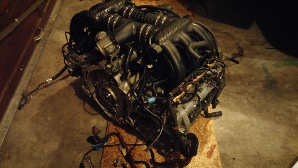
It went together in a pretty straight forward fashion, except one thing and I need the input of anyone who can assist:

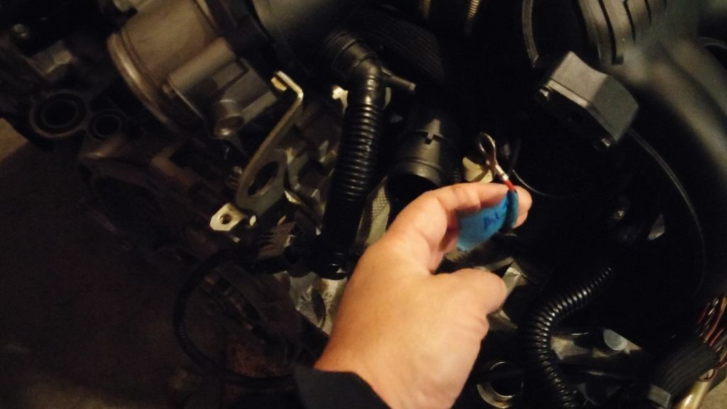
I have one wire terminal which I would like to POSITIVELY identify. I have it labeled as if it came from the Alternator, but you know how when you lay a previously installed wiring bundle in place things just kind of flop out near where they go?

Well this one flops over by my starter motor. A single red wire with a round terminal to either a starter or alternator would not normally cause me any pause at all. But the possibility that it could be either is now a problem. This is a MUCH easier place to reach with the engine on the ground than it is once it is installed.

There another branch of the wiring harness which has a connector on the back of the alternator, and this loose wire is approximately the same length and with careful routing I could connect it to the large terminal on the alternator.

This next lousy photo shows the terminal.
flaps10 is offline   Reply With Quote
Old 04-01-2015, 03:56 PM   #119
Registered User
 
flaps10's Avatar
 
Join Date: Jul 2014
Location: Tacoma
Posts: 430
Cancel that last request. Thanks to Wayne's efforts of taking pictures for his book I was able to find a very clear shot of the back of the alternator and that wire definitely goes there.

Crisis avoided. Plus maybe some smoke.
flaps10 is offline   Reply With Quote
Old 04-01-2015, 04:10 PM   #120
Registered User
 
Join Date: Jan 2015
Location: Moore, Ok
Posts: 105
Garage
I'm so excited to see it in!!!

Redboxs is offline   Reply With Quote
Post Reply


Posting Rules
You may not post new threads
You may not post replies
You may not post attachments
You may not edit your posts

BB code is On
Smilies are On
[IMG] code is On
HTML code is On
Trackbacks are On
Pingbacks are On
Refbacks are On


All times are GMT -8. The time now is 04:47 PM.


Powered by vBulletin® Version 3.8.7
Copyright ©2000 - 2024, vBulletin Solutions, Inc.
Content Relevant URLs by vBSEO 3.6.0
Copyright 2024 Pelican Parts, LLC - Posts may be archived for display on the Pelican Parts Website -    DMCA Registered Agent Contact Page