Quote:
Originally Posted by flaps10

I was mostly poking fun at rear engine cars as opposed to mid engine cars not trying to roast the M96 as an oversize boat anchor. I'll try to stay on topic.
|
I took it as humorous. Great thread; keep it up.
__________________
2000 Boxster S, 6 speed, Sport Package, Litronics, LED tail lights, LNE IMS-B, OBC, Skybreaker wind deflector, Arctic Silver/Graphite Grey
|


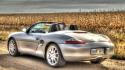 Boxster S
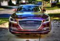 Genesis 3.8


 Threaded Mode


