 11-28-2018, 01:34 PM
|
#1
|
|
Registered User
Join Date: Nov 2015
Posts: 27
|
Need a little help making sense of Hi-Fi factory stereo wiring (2004 non-Bose)
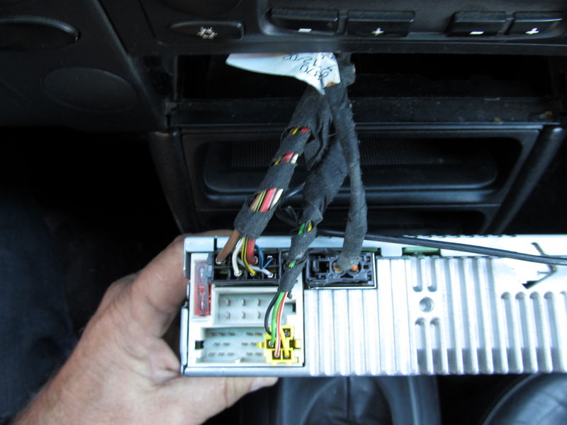
I'm working on a 2004 Boxster with the Hi-Fi stereo option. I have a factory 4 channel Becker (non-Bose) amplifier with the MOST fiber optic connection to the Becker CDR-23. There is no rear speaker deck. I am planning on replacing the head unit and amplifier. I've searched the forums and read these guides:
https://www.renntech.org/forums/topic/19616-porsche-boxster-avic-d3-installation-instructions/
https://www.pelicanparts.com/techarticles/Boxster_Tech/88-ELEC-Radio_Install/88-ELEC-Radio_Install.htm
Installing Pioneer AVH 4000NEX with Euro Motorsport Double DIN
There are a few things I still don't understand. Now from what I understand the factory amplifier gets power and audio signal from the MOST bus connection. Is that correct? So can someone explain to me what the yellow "C" connector is doing with line outputs? Isn't this what the MOST bus is for? I was planning on running RCA cables directly from my new head unit to the new amplifier but these guides use a harness to connect to the RCA out on my head unit to this yellow C connector. Where exactly does this go? I know that I still have to use this to the remote amp turn on wire but the rest I don't understand.
|

|

|
|
11-29-2018, 04:20 AM
|
#2
|
|
Registered User
Join Date: Feb 2017
Location: texas
Posts: 160
|
I went through this with my 2003 with the same setup. Simply replaced the factory amplifier with a new one. Your replacement Head unit will need to be connected to the new amplifier. The problems are all about power. Fiber optics (MOST) are light signals and do not convey power. You will most likely abandon the YELLOW MOST fibers. You will need to find ignition switched power for you head end and make sure that you connect the head end to the amplifier so it provides sound and whatever on off and operating power the new amplifier is looking for. Good Luck.
Last edited by obthomas; 11-29-2018 at 04:26 AM.
|
|
|
|
|
11-29-2018, 08:28 AM
|
#3
|
|
Registered User
Join Date: Jun 2013
Location: Nanaimo, Vancouver Island, British Columbia, Canada
Posts: 916
|
|
|
|
|
|
11-29-2018, 09:57 AM
|
#4
|
|
Registered User
Join Date: Nov 2015
Posts: 27
|
Maybe I need to rephrase the question. On the factory setup, if audio signal is conveyed from the head unit to the amplifier via the MOST connector then what does the yellow connector actually do?
Yellow / Red Left Rear Line Output Positive Yellow Connector C - Pin 1
Red / Blue Right Rear Line Output Positive Yellow Connector C - Pin 2
Brown / Blue Common Audio Ground Yellow Connector C - Pin 3
Green / Red Left Front Line Output Positive Yellow Connector C - Pin 4
Violet / Red Right Front Line Output Positive Yellow Connector C - Pin 5
Black / Red 12 Volt Switched Power Yellow Connector C - Pin 6
|
|
|
|
|
11-30-2018, 04:36 AM
|
#5
|
|
Registered User
Join Date: Feb 2017
Location: texas
Posts: 160
|
The yellow connector contains the links between the Porsche radio and the Porsche amplifier. This link will not connect your new radio and amplifier
connect your new radio and amplifier following instructions with the new radio and amplifier using harness and wires with the new equipment.
You will be missing a switched 12 volts to the radio that you will need to find and provide.
Speakers connect to your new amplifier in the usual way.:dance:
|
|
|
|
|
11-30-2018, 07:18 AM
|
#6
|
|
Registered User
Join Date: Jun 2014
Location: LB, Germany
Posts: 1,522
|
Sorry you're totally wrong.
This is a CDR23.
The external amp gets his audio signal via MOST-Bus. That is the connector in the right top on the picture. MOST-Bus is an audio bus only. It doesn't switch anything on or off.
The external amp (HAES or BOSE) has it's own power supply cables and fuse and CAN bus wakeup.
The power on by the car get both components via interior CAN BUS signal (wake up signal). If you want to power on / off aftermarket audio components like the 986 does via putting the key in the ignition switch you'll need an adapter that generates that internal bus signal to a B+ switch signal.
Also there is a connection between the IC and the CDR23 via interior CAN BUS that shows radio stations and so on the IC.
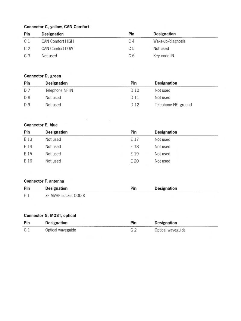
The yellow connector is for interior CAN bus / wake up and unit programming. Don't mess with the yellow connector, else you will have CAN bus problems.
Regards, Markus
__________________
My Porsche keyfob, instrument cluster and alarm ecu repair service: https://sportwagendoktor.de
Last edited by Smallblock454; 11-30-2018 at 02:49 PM.
|
|
|
|
|
11-30-2018, 01:00 PM
|
#7
|
|
Registered User
Join Date: Nov 2015
Posts: 27
|
Thank you so much for this. I knew things were not making any sense. So is the yellow connector fine left alone and not connected to anything? Some of the other guides suggest that PIN 6 is connected to the blue/white wire on the head unit for antenna control maybe? Should this just be left out completely?
Black / Red 12 Volt Switched Power Yellow Connector C - Pin 6
Quote:
Originally Posted by Smallblock454

Sorry you're totally wrong.
This is a CDR23.
The external amp gets his audio signal via MOST-Bus. That is the connector in the right top on the picture. MOST-Bus is an audio bus only. It doesn't switch anything on or off.
The external amp (HAES or BOSE) has it's own power supply cables and fuse and CAN bus wakeup.
The power on by the car get both components via interior CAN BUS signal (wake up signal). If you want to power on / off aftermarket audio components like the 986 does via putting the key in the ignition switch you'll need an adapter that generates that internal bus signal to a B+ switch signal.
Also there is a connection between the IC and the CDR23 via interior CAN BUS that shows radio stations and so on the IC.
The yellow connector is for phone, microphone and interior CAN bus. Don't mess with the yellow connector, else you will have CAN bus problems.
Regards, Markus
|
|
|
|
|
|
11-30-2018, 02:44 PM
|
#8
|
|
Registered User
Join Date: Jun 2014
Location: LB, Germany
Posts: 1,522
|
See attachment.
__________________
My Porsche keyfob, instrument cluster and alarm ecu repair service: https://sportwagendoktor.de
|
|
|
|
|
11-30-2018, 09:57 PM
|
#9
|
|
Registered User
Join Date: Nov 2015
Posts: 27
|
Thank you again for the information. One last question about that connector. It appears that the C4 pin (wake up/diagnosis) is a white/red wire that goes to the amplifier. If this is true I can use it to connect my remote turn on from my new head unit to turn on my new amplifier. I just want to make sure it does not go anywhere else.
|
|
|
|
|
12-02-2018, 05:25 AM
|
#10
|
|
Registered User
Join Date: Jun 2014
Location: LB, Germany
Posts: 1,522
|
Connector C, C4 is the wake up from the CDR23 to the HAES amp. To make shure just measure on the CDR23 and on the amp if you get 12V when the CDR23 is turned on. But this wire does go also to a diagnosis port.
I wouldn't use or cut any OEM wiring harness for setting up a new system. Just leave it alone and make your own harness including speaker harness. So you can always go back to stock without any problems and you don't mess anything up – for example a bus system.
Regards, Markus
__________________
My Porsche keyfob, instrument cluster and alarm ecu repair service: https://sportwagendoktor.de
|
|
|
|
|
12-02-2018, 11:51 AM
|
#11
|
|
Registered User
Join Date: Nov 2015
Posts: 27
|
I suppose I do have to run the RCA cables to the amplifier anyway so adding the wake up wire to go with it is not a big deal.
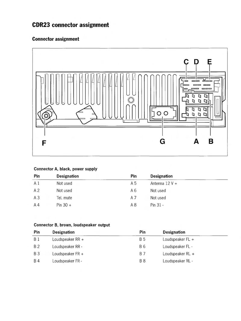
I WAS however planning on using the 12V+ constant on pin 4 of the black connector and pin 8 ground on the same connector for the new head unit. Everything else I would wire separate like the ACC power on and the like. I do have a question about pin 5 however for the antenna 12+. Do I need to supply power to this for my FM radio to get good signal? Is this a powered antenna? Is it hooked up to the same wake up wire I am going to run to my amp?
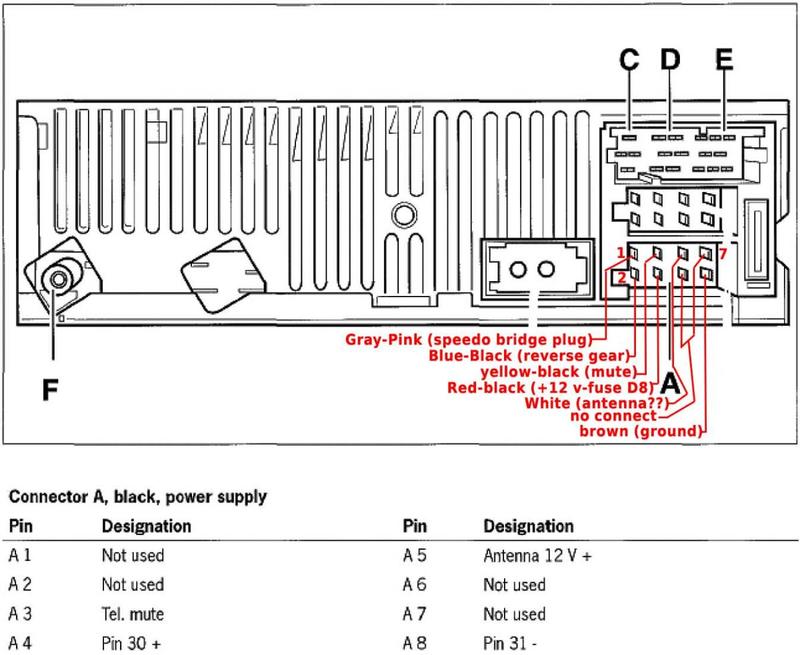
For future reference even though the CDR-23 didn't use them there were a few wires not accounted for and I found pin out for the black connector from this thread that accounts for them.
https://www.renntech.org/forums/topic/25829-becker-cdr-23-pinout-or-connector-wiring-diagram/
|
|
|
|
|
04-07-2019, 01:56 PM
|
#12
|
|
Registered User
Join Date: Nov 2015
Posts: 27
|
For future searches that diagram in my last post was spot on. I was able to use A4 for constant power, A2 to give power to my reverse camera and turn on reverse on my head unit, A5 for the power antenna and amplifier turn on, and A8 for ground. Everything is working flawlessly. I don't understand why people complain about this ground as it is the factory ground for the factory radio and has no issues. Anyway it works great if anyone is curious.
|
|
|
|
|
10-26-2022, 11:56 AM
|
#13
|
|
Registered User
Join Date: Apr 2021
Location: Lansing, MI
Posts: 373
|
I need to dig to my radio wiring... it appears that the way it was wired by the previous owner is causing problems programming the new key (well, remote, the key works).
I am glad this thread exists.
Any suggestions in the meantime are welcome
__________________
Current rides: 2003 Porsche Boxster MT (me), 2019 Bolt LT (me), 2015 Audi Q5 (wife), 2008 VW Rabbit (2.5 inline 5, MT, well, for kid... but you now, it is the 5 straight)
Previous: 2014 Fiat 500e, 2016 KIA Forte5 SX, 2016 Fiat 500X, and some old days: Trabant, Fiat 126p...
|
|
|
|
 Posting Rules
|
You may not post new threads
You may not post replies
You may not post attachments
You may not edit your posts
HTML code is On
|
|
|
All times are GMT -8. The time now is 03:49 AM.
| |


 Hybrid Mode


