Go Back   986 Forum - The Community for Porsche Boxster & Cayman Owners > Porsche Boxster & Cayman Forums > Boxster General Discussions

Post Reply
 
LinkBack Thread Tools Display Modes
Old 04-06-2014, 02:57 PM   #1
Registered User
 
Benjamin's Avatar
 
Join Date: May 2012
Location: Kalamazoo, MI
Posts: 149
Garage
After doing some more reading, you are correct about the bank numbers. Cylinder 1 is behind the passenger seat (left hand drive) and cylinder 4 is behind the drivers seat. I think you might be right about the chain locations as well.

Attempting to interpret the LN instructions: It kind of sounds like you can lock down either side, bank 1 locks in the front and bank 2 locks on the flywheel side. Whichever bank you choose, remove the IMS to cam tensioner for that bank and the crank to IMS tensioner. Then optionally loosen or remove the other bank's tensioner.

I'm still not clear what keeps the non locked bank's cams from moving when that tensioner is (optionally) loosened or removed.
__________________
2000 986 S - "The Black Widow"
Benjamin is offline   Reply With Quote
Old 04-07-2014, 12:12 PM   #2
Registered User
 
Benjamin's Avatar
 
Join Date: May 2012
Location: Kalamazoo, MI
Posts: 149
Garage
After doing some more reading, a lot of thinking, and a bit of sketching, I think I have it ironed out. It makes sense to lock down the bank 1 exhaust cam and remove the bank 1 IMS to cam tensioner, as well as the crank to IMS tensioner. I see little to no value in removing the bank 2 tensioner because of it's location and potential skewing effect on the IMS bearing end of the IMS. The reason to remove the tensioners is so that the end of the IMS will not be pulled askew when the bearing is removed. With the IMS bearing removed, the flywheel end of the shaft will have quite a bit of potential for movement (hence the need to remove or greatly loosen the two tensioners mentioned above). The bank 2 chain is on the pulley end and is subject to almost no movement at all and any tension put on the IMS shaft would result in comparatively little movement on the IMS bearing end. Here is a sketch I threw together as to how I understand the internal components to be laid out. (Obviously things aren't to scale and it's lacking quite a bit of detail with the cams, etc, but you get the idea)


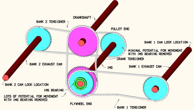
The intake cams were left off for clarity and due to laziness.
__________________
2000 986 S - "The Black Widow"

Last edited by Benjamin; 04-08-2014 at 07:07 PM.
Benjamin is offline   Reply With Quote
Post Reply


Posting Rules
You may not post new threads
You may not post replies
You may not post attachments
You may not edit your posts

BB code is On
Smilies are On
[IMG] code is On
HTML code is On
Trackbacks are On
Pingbacks are On
Refbacks are On


All times are GMT -8. The time now is 10:22 AM.


Powered by vBulletin® Version 3.8.7
Copyright ©2000 - 2025, vBulletin Solutions, Inc.
Content Relevant URLs by vBSEO 3.6.0
Copyright 2025 Pelican Parts, LLC - Posts may be archived for display on the Pelican Parts Website -    DMCA Registered Agent Contact Page