 06-05-2011, 01:31 PM
|
#1
|
|
Registered User
Join Date: Mar 2007
Location: Ohio
Posts: 2,032
|
Front wheel bearing on a '01S
Okay, I have finally found some time to dive into my front wheel bearing job. Haven't gotten too far...at this point, I have the wheel off, as well as the brake caliper and the rotor.
I'm a bit confused as to what's next. In that I have the SIR bearing/hub tool, I am inclined to do this without removing the wheel bearing carrier from the car. I have Wayne's 101 Projects book (which is a good book), but he just mentions that this can in fact be done on the car. It's not real clear to me just what needs to be disconnected prior to jumping into the bearing removal with the SIR.
At the stage I am at, what exactly has to be done before I start removing the bearing?
|

|

|
|
06-05-2011, 02:01 PM
|
#2
|
|
Registered User
Join Date: Oct 2008
Location: Gilbert, AZ
Posts: 266
|
IMO, its worth removing the upright (spindle assembly) and have a shop press out the old bearings and press in the new ones. The downside to doing this is you have to get at least a front end wheel alignment, but if you haven't had one done in a while, it could likely benefit from an alignment anyway.
|
|
|
|
|
06-05-2011, 07:36 PM
|
#3
|
|
Registered User
Join Date: Mar 2007
Location: Ohio
Posts: 2,032
|
Yeah, but (1) It hasn't been all that long since I had an alignment done---I would think it should still be good, and (2) the whole reason I got the SIR tool was to avoid having to remove the bearing carrier and go to a machine shop to hydraulically press out the bearing. If possible, I wanna do this whole operation in my garage.
I'm new to this, but I guess I need to narrow my focus. (It's a bit frustrating, but DIY write-ups seem to assume readers DON'T have the SIR tool---or that, if they do, they're already accomplished enough mechanics NOT to need a lot of guidance online...) Okay, what with having that tool in hand, here's my questions boiled down to the minimum:
1) Do I need to remove the 3 strut tower nuts at the top (inside the frunk)?
2) (Maybe related) Do I need a spring compressor (as suggested by one online DIY write-up)? If I remove the 3 above-mentioned nuts but not the one centered between them at the top, the spring remains compressed, right?
3) Do I need a ball joint separator? (If so, where's a reasonably priced, easily had, fairly universal one to be found?)
Thanks in advance for any guidance.
|
|
|
|
|
06-06-2011, 06:33 AM
|
#4
|
|
Registered User
Join Date: Sep 2004
Location: Atlanta
Posts: 1,820
|
do NOT pull the wheel carrier and do NOT loosen the strut top mount. you're over thinking things here. have you removed the 32mm nut inside the hub spindle? it's part 6 in the diagram below. if you have NOT removed this, put your wheel back on & lower the car to the ground. remove the wheel center cap & remove this 32mm nut. then jack up the car & remove the wheel again. after that, here is your procedure:
1. remove nut (6) and ABS stator (5)
2. pull hub (9) with SIR horseshoe attachment
3. remove bearing cover (7)
4. pull bearing with SIR puller
5. press in bearing with SIR puller
6. install bearing cover
7. press in hub with SIR puller
8. loose install ABS stator with NO nut
9. install brake caliper & wheel
10.lower car
11.install nut (6) with loctite; torque to 339 ft-lb.
have fun!
|
|
|
|
|
06-06-2011, 07:02 AM
|
#5
|
|
Registered User
Join Date: Mar 2007
Location: Ohio
Posts: 2,032
|
That's it? No removing the end link, no loosening anything on the control arm, no disconnecting the tie rod? Don't get me wrong, that sounds good...but there's conflicting reports out there on how much disassembly is required. Following your recommendation, does the bottom of the strut not get in the way?
BTW, yes, I do have the 32 mm nut off.
And now a more elementary question I should have asked before (sorry). When I spin the hub, the bearing really doesn't feel/sound bad at all. In fact, to my untrained ear (and fingertips), it seems pretty good. Can bearings start to go, to the point they'll make an audible noise when driving (with top up, especially at relatively slow speeds, especially when turning, especially turning to the left) and yet still feel/sound pretty good once the wheel, caliper and rotor are off?
|
|
|
|
|
06-06-2011, 07:41 AM
|
#6
|
|
Registered User
Join Date: Sep 2004
Location: Atlanta
Posts: 1,820
|
trust me; i've done dozens of these. the SIR makes it easy.
EDIT: to answer your other question, you can't tell if a bearing is bad just by trying to wiggle the spindle. sometimes there is obvious play, but sometimes there is not.
|
|
|
|
|
06-06-2011, 08:58 AM
|
#7
|
|
Schatten-Baum-Mechaniker
Join Date: Mar 2005
Location: Mississippi
Posts: 242
|
I thought the strut insert blocked you from removing #5. At least it did on my 2000 S.
__________________
Tommy
2000 Boxster S
1973 914
|
|
|
|
|
06-06-2011, 09:18 AM
|
#8
|
|
Registered User
Join Date: Sep 2004
Location: Atlanta
Posts: 1,820
|
Quote:
|
Originally Posted by tommy986
I thought the strut insert blocked you from removing #5. At least it did on my 2000 S.
|
i haven't ever run into that problem.....
well, frodo, if you run into that issue, remove the sway bar link bolt from the top of the wheel carrier. loosen the lower control arm bolt. this will allow you to slide the wheel carrier a bit lower on the strut to clear the stator IF you have a clearance issue.
|
|
|
|
|
06-06-2011, 04:45 PM
|
#9
|
|
Registered User
Join Date: Mar 2007
Location: Ohio
Posts: 2,032
|
Well, yeah, I did run into that issue, unfortunately. The way it is now, there's no way to get the wheel spindle/ABS (#5 on your pic) piece out. (Things may have changed between '99 and '01?)
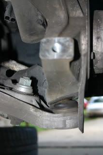
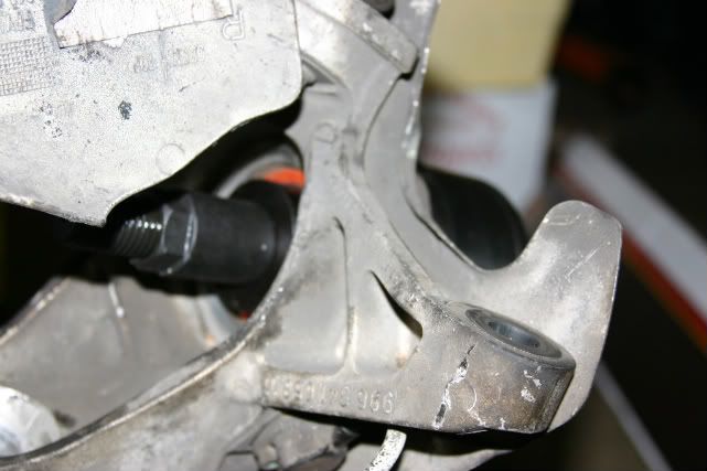
Okay, Insite, onto what you were recommending. I loosened the top end-link bolt at the top of the wheel bearing carrier:
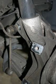
Doesn't that also help hold the wheel bearing carrier to the strut? I should push that bolt all the way through and out (ie, to the left in my pic)?
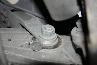
Keeping in mind that I'm an admitted noob, here's where I also start to run into terminology problems. You say to loosen the lower control arm bolt. Now 101 Projects refers to the components of the suspension as the 'wishbone' and 'control arm'. Bentley calls the same pieces the 'transverse control arm' and the 'diagonal control arm.' They're all the same thing, right? So when you talk about loosening the lower control arm bolt, are you talking about the bolt by the nickle (next to the ball joint)? If so, again: do I take it all the way out or just loosen it?
I know these are idiotic questions, I just want to do this right the first time... ")
|
|
|
|
|
06-06-2011, 06:55 PM
|
#10
|
|
Registered User
Join Date: Sep 2004
Location: Atlanta
Posts: 1,820
|
my car has coilovers, so that may have been the difference.....
in your first picture, remove the bolt completely. you want the wheel carrier to slide down the strut. if you can make this happen without doing anything else, then GOOD.
if the wheel carrier will NOT slide down the strut after you've removed that bolt, then you need to only LOOSEN the control arm bolt. in your last picture, the quarter is sitting on the control arm. trace it to the left of the picture; there is a single bolt that holds the control arm to the subframe under the car. if you loosen it, the control arm will move & allow you to lower the wheel carrier enough to get the ABS stator out of the upright.
|
|
|
|
|
06-07-2011, 09:42 PM
|
#11
|
|
Registered User
Join Date: Mar 2007
Location: Ohio
Posts: 2,032
|
OK, here's where I am now. (I'm workin' on this in short bursts, when I get home from work. Not my DD, no huge hurry...except the weather is suddenly BEAUTIFUL, perfect driving weather, unlike what it's been for the past several months. So maybe I AM in a hurry.)
Per the above recommendations, got the endlink disconnected from the wheel bearing carrier, and got the inner bolt loosened on the control arm:
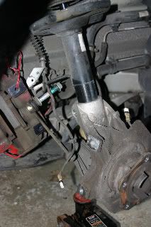
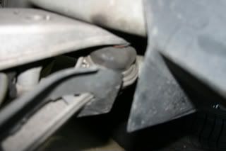
You can see how far the carrier has dropped on the strut. Here's the problem:
In the first pic, you can see I've gotten the carrier lowered by maybe 2" (see the horizontal line around the strut, separating dirty areas from clean, black areas)...it's still not enough. Looking at the second pic (taken from behind the wheel bearing carrier, ie from the inside looking out), I think I probably still need maybe another inch before I have any chance of slipping the wheel spindle/ABS piece (#5 on earlier schematic pic) out to start the actual wheel bearing work. The bottom of the strut (for the uninitiated, it's the more-or-less vertical black cylinder in the upper left part of the pic) is still in the way.
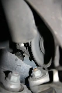
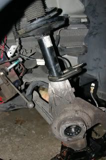
I've been tapping on the carrier (light hammer taps, with a piece of wood taking the blows) to get it as far as I have. My question now is whether or not I'm going to create problems with either the LCA ball joint:
...or the ball joint at the innermost end of the diagonal control arm:
It may be hard to tell from the photos, but they're both getting some pretty significant angles to them. (The carrier tapped down to where it is pretty easily; now progress is getting tough.) I'm really trying NOT to break anything here.
I guess my options are:
1) disconnect the strut at the top, which might give me some more play.
2) unbolt the bolts at the ball joint and/or at the inner end of the diagonal control arm.
I was trying to avoid #1, because I think everything then gets all loosy-goosy which, I would think, would make extracting the hub and bearing more difficult. (I'm working alone much of the time.)
Are there any "issues" involved with #2 other than just wrenching off the nuts? No ball joint tool involvement? (I don't have one---though I suppose I could pick one up.)
Would a spring compressor (available at the local Auto Zone or Advanced Auto) be of any help?
Any advice appreciated.
|
|
|
|
|
06-08-2011, 04:45 AM
|
#12
|
|
Registered User
Join Date: Sep 2004
Location: Atlanta
Posts: 1,820
|
don't split the ball joint; it never goes well unless you have the nice handy porsche tool. remove the bolt that holds the control arm to the subframe (you loosened this earlier). that should give you enough play. i don't think you'll need to remove the diagonal link, but i've been wrong before....
you have a better view there; if you think the diagonal link is a problem, remove the bolt in the center of the control arm BEFORE you separate the control arm from the subframe. once you have enough room, use a c-clamp to pinch the upright to the strut (put the c-clamp where the drop link goes). i think you'll get better leverage w/ the SIR tool if the wheel carrier is still attached to the strut.
|
|
|
|
|
06-08-2011, 07:09 AM
|
#13
|
|
Schatten-Baum-Mechaniker
Join Date: Mar 2005
Location: Mississippi
Posts: 242
|
I think it's the diagonal that is limiting the downward movement at this point.
Remove the bolt next to the nickel in the pictures you took. Then slide the diagonal fork out of the way.
to answer your questions
#1 yes, removing the strut bolts at the top along with the diagonal brace will allow the strut to drop down, then you can swing it out from under the fender and pull the strut out of the carrier. I was replacing the struts at the same time, so this is what I did.
#2 I also just removed the ball joint bolt and pulled the carrier off the car. I had previously done the rear ball joints with the carrier on the car. After wrestling with that I had decided I wanted to do the fronts on my work bench.
At some point you will need to get the ball joint removal tool if you plan to continue to work on the car. The tool I use is KD 3916. I found mine at NAPA, but a quick online search shows that SEARS has it now for $20.
__________________
Tommy
2000 Boxster S
1973 914
Last edited by tommy986; 06-08-2011 at 07:40 AM.
|
|
|
|
|
06-08-2011, 07:30 PM
|
#14
|
|
Registered User
Join Date: Mar 2007
Location: Ohio
Posts: 2,032
|
Actually, when the most recent pics were taken, I had already removed the bolt that holds the control arm to the subframe. (Just loosening it really didn't seem to do much.)
On control arm terminology I sometimes get a little screwed up, so I guess I'll go with what Bentley says: "transverse" being the one that is perpendicular to the long axis of the car, ie the one with the ball joint at the bottom of the wheel carrier. "Diagonal" is the other, the one that bolts onto the center of the transverse.
I think you're right, Tom, I think it is the diagonal portion of the control arm that is holding things up. You both recommended I remove the bolt that holds the two parts together (ie "next to the nickel") and that makes sense to me. Insite, you recommended I do that BEFORE I separate the control arm from the subframe. I assume you mean before I remove the bolt holding the transverse control arm (not the diagonal) to the subframe, right? If so, as I indicated above, it's too late for that.
What's the problem that you run into doing it after instead of before? Is it just tougher to wrestle the two arms apart from each other? I could probably put the jack under the inner end (where the bolt has already come out) and lift it back up to approximately where it was.
If you're reading between the lines here you may have already accurately concluded I got NOTHING done on this today, other than reading your suggestions. It was a really tough, really long day at work---I got home just too bushed to even think about working in the garage. The fact that it was like 90 out didn't help matters...
|
|
|
|
|
06-09-2011, 04:48 AM
|
#15
|
|
Registered User
Join Date: Sep 2004
Location: Atlanta
Posts: 1,820
|
i looked at my car in the air yesterday; my coilovers don't block access to the ABS stator. sorry for the misinormation early on!
|
|
|
|
|
06-09-2011, 09:54 PM
|
#16
|
|
Registered User
Join Date: Mar 2007
Location: Ohio
Posts: 2,032
|
Okay, if anybody's still keeping track of this, my progress:
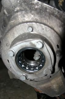
Got the hub pushed out, breaking up the bearing in the process. Doesn't look too bad, but I haven't looked too closely yet. (Hopefully it IS the source of my noise!)
As another member here (JFP) once remarked, by the time you get to the point where you can use the SIR, you're a connection or two away from having the whole wheel bearing carrier off...at which point, you could remove it and take it to a machine shop to do the pressings. However, like I said before, I wanted to be able to do everything in my very own garage. So far, the SIR is working like a charm. It's so agreeable to be able to use a tool that does exactly what it's designed to do, with not a lot of effort, without having to jury-rig anything.
I ended up uncoupling the bolts of the control arms (diagonal and transverse). (I figured out why Insite recommended loosening the bolt that holds the two together, at the middle of the transverse BEFORE removing the bolt that holds the transverse to the subframe: Once the subframe bolt is removed, you can no longer crank on the bolt in the middle (and it's on pretty tight), because the whole thing moves around too much. Are those (the ends of both parts of the control arm) going to be a bear to get back into place in the subframe?? Guess I'll find out...
I've noticed in some of the DIY write-ups recommendations against reusing some of the bolts in reassembling certain suspension components. By kid calls BS, but I was curious what some people here thought. For those of you who have taken apart suspension, brake calipers, etc, have you re-used all the nuts and bolts? If not, which specific ones should one use new ones on? Wouldn't slapping a little Loctite on accomplish the desired result?
|
|
|
|
|
06-11-2011, 02:24 PM
|
#17
|
|
Registered User
Join Date: Mar 2007
Location: Ohio
Posts: 2,032
|
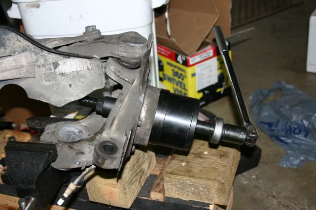
Who's used the SIR tool?
For anyone who's used the SIR tool (or anyone who just happens to know), is this the correct set-up for pushing the bearing out? That's a 14" breaker bar and I'm pretty much putting my whole weight (175 lb) on it to get it to turn even a little. Should it be that tough?
|
|
|
|
|
06-11-2011, 02:48 PM
|
#18
|
|
Registered User
Join Date: Feb 2005
Location: It's a kind of magic.....
Posts: 6,660
|
Looks right.......

Assuming you have lubed the theaded sections of the tool, it should require some effort to get it started, then release and come out. Normally, I would use an impact wrench to get it moving.
__________________
Anything really new is invented only in ones youth. Later, one becomes more experienced, more famous and more stupid. - Albert Einstein
Last edited by JFP in PA; 06-11-2011 at 02:51 PM.
|

|
|
|
06-11-2011, 06:49 PM
|
#19
|
|
Registered User
Join Date: Feb 2005
Location: It's a kind of magic.....
Posts: 6,660
|
I was checking back on your post to see how you made out when I noticed something in your second picture; is that exactly how the tool is set up when you encountered the resistance? Reason I ask is that I just notice the center bolt in your pic is protruding out quite a bit (the large silver thrust wash is not in contact with the tools cup face as it is in my photo and the one below). If that is the case, something is not set correctly and you should disassemble the tool and reset it so that the thrust washer is up against the tool when you start to tighten it; that may help with your issue
.

__________________
Anything really new is invented only in ones youth. Later, one becomes more experienced, more famous and more stupid. - Albert Einstein
|
|
|
|
|
06-11-2011, 08:02 PM
|
#20
|
|
Registered User
Join Date: Mar 2007
Location: Ohio
Posts: 2,032
|
Too late...the task is accomplished and (probably) the damage is done. I noticed when I set it up: the piece you referred to (they call it the "Support Disc #5") would slide past the threads of the big bolt, but then butted up against a narrow lip that was the beginning of the thread-less shaft. That's why, in the second pic of my last post, you can see like 1 1/2" of shaft between the narrow support disc (black) and the thrust bearing (silver colored).
I cranked the hell out of the thing (adding a piece of pipe into the mix---making my breaker bar 2' long or better. Leverage is a wonderful and dangerous thing, ain't it? ). It turned, but only with A LOT of effort. I kept stopping, removing the crescent wrench (the stopper, on the inside bolt head), looking for progress on bearing movement, oddly never really seeing any. I hadn't gotten far before I realized that it was the 1 1/2" gap that was compressing, the bearing itself not moving a whit. At that point I realized something was not right but figured I was more or less committed---any damage done to the support disc was done, and wasn't going to get any worse by my continued effort. AND, once that 1 1/2" gap disappeared altogether and the support disc contacted the thrust bearing, something else had to start moving, presumably the bearing. That proved to be true, and ultimately the bearing came out cleanly.
Now, however, I have the support disc semi-permanently wedged onto the bolt against the thrust bearing:
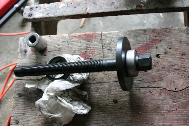
It IS tight. I might be able to carefully beat it out with a hammer (buffered with a block of wood), but may just leave it for now until it becomes apparent I even need to get it off. As far as I can tell, I may in fact not need to do that, may still be able to use the tool as is. But I definitely could be wrong about that...time will tell. (My peanut brain can't think that far ahead!)
In all honesty, I don't know what went wrong. The support disc was oriented right, because it had a thin lip that fit nicely into the next piece (the wide spacer sleeve). It just seemed like the hole in the center was not quite as big as it should have been.
Oh well, onto the next step...
|
|
|
|
 Posting Rules
|
You may not post new threads
You may not post replies
You may not post attachments
You may not edit your posts
HTML code is On
|
|
|
All times are GMT -8. The time now is 09:08 PM.
| |


 Linear Mode


