Bill, take a look at these two posts and see if you can sort it out:
Quote:
Originally Posted by 78F350

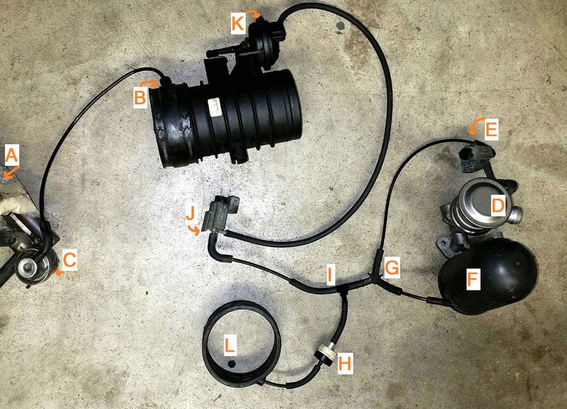
In regard to the vacuum connections, here's that diagram, created with actual parts from a scrapped 2001 2.7L.

Notes:
-This picture shows what connections have to be made, the actual order of connections to the Y fittings (I) and (G) are not critical.
-The Tiptronic cars will have a 4-way connection at (I) or (G) with a line running to a changeover valve on the transmission.
It looks like a mess of tubes and parts, but in function it is fairly simple.
This shows 3 vacuum powered components: SAI, Resonance Flapper, and Fuel Pressure Regulator. Brake booster vacuum system is not shown.
SAI: Vacuum source -> electric change-over valve (E) -> change-over valve (D).
Resonance Flapper: Vacuum source -> electric change-over valve (J) -> vacuum unit (K).
Fuel Pressure Regulator: Vacuum source (B) -> Pressure regulator (C) -> injector valves (A).
Rubber sleeves (L) and (B) are the source of vacuum from the intake. (H) is a check valve. (F) is the vacuum reservoir. |
Note that (L) in the above diagram is placed on the junction to the right of the throttle body.
Quote:
Originally Posted by jsceash

On a 2003, Driver side intake manifold has a vacuum switch between cylinder 4 and 5 intake risers. A line comes off the bottom of that switch and goes to the Y connector near the vacuum tank the other end goes to a connection on the underside of the passenger side plenum collar. The same switch has a second tube that goes to the diaphragm you pictured. I have an engine apart now and can probably get you a couple pictures
 |
Hope that solves it for you.