 02-24-2018, 08:21 AM
|
#101
|
|
Registered User
Join Date: Oct 2017
Location: Portland OR
Posts: 100
|
Quote:
Originally Posted by B6T

Yes the tensioner is in the stock location but the belt routing is entirely different and follows what I was saying before.
Anyway, just trying to help out and prevent a headache for you in the future.
 |
Ah, got it. Thanks for the pic, I had gotten so excited that things fit I lost track of this point. My guess is this will work fine because I have taken almost all the load off the system, it was designed to run with the full load of AC, PS, cooling fan and the alternator. Now all I have is the alternator, Im guessing load is a 10th of what it was so think it will work. I have spent years working on NSXs with Comptech supercharger kits, they also had the belt tensioner on the wrong side of the belt run. The crazy thing with them was they would work fine up to 6 lb. of boost and then just gently slip and hold that boost level. I make locking tensioner for that application that replace the spring loaded tensioner and customers will see 1 lb. + in boost at high RPM.
Thanks again...forest through the trees.
|

|

|
|
02-24-2018, 08:44 AM
|
#102
|
|
Registered User
Join Date: Aug 2015
Location: Waterloo, Ontario
Posts: 193
|
No problem man.
I doubt it would be a problem based on what you said but you don't want to have to worry about it.
On the subject of supercharging... the guys doing this swap and removing PS and AC sure are opening up a lot of space for a centrifugal supercharger on the LH side of the engine.
Do you use CAD or Solidworks for any of your designs?
|
|
|
|
|
02-24-2018, 08:47 AM
|
#103
|
|
Certified Boxster Addict
Join Date: Nov 2010
Location: Los Angeles
Posts: 7,669
|
While a V-8 conversion isn't something that I think I'd ever do, I have enjoyed following your progress and definitely appreciate the effort that has went into this build.
Keep up the good work!
__________________
1999 996 C2 - sold - bought back - sold for more
1997 Spec Boxster BSR #254
1979 911 SC
POC Licensed DE/TT Instructor
|
|
|
|
|
02-24-2018, 08:05 PM
|
#104
|
|
Registered User
Join Date: Sep 2014
Posts: 116
|
Quote:
Originally Posted by titaniumdave
6 rib? I had the hardest time finding short 7 rib belts, D&D has a few option.
|
I'm pretty sure my pulleys are 6 rib. 2001 AUX engine code from an A8. If not, with the reduced stress on the belt from only running the alternator, I'm sure it will survive.
|
|
|
|
|
02-25-2018, 09:39 AM
|
#105
|
|
Registered User
Join Date: Oct 2017
Location: Portland OR
Posts: 100
|
Quote:
Originally Posted by B6T
No problem man.
Do you use CAD or Solidworks for any of your designs?
|
I have the hard points in AutoCAD, but Im a Luddite and have them only in 2D.
|
|
|
|
|
02-27-2018, 06:08 PM
|
#106
|
|
Registered User
Join Date: Oct 2017
Location: Portland OR
Posts: 100
|
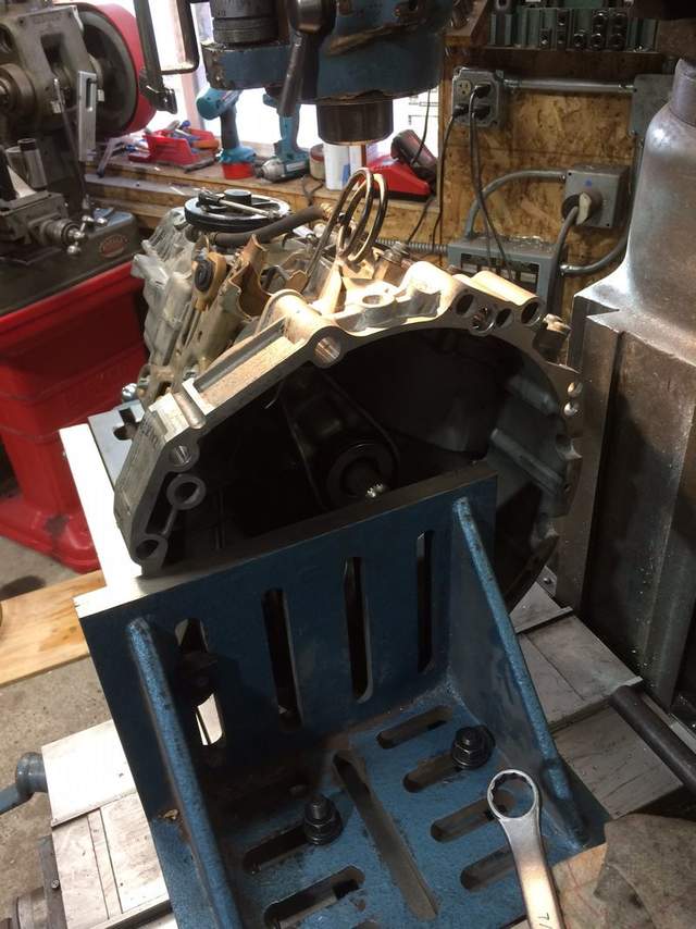
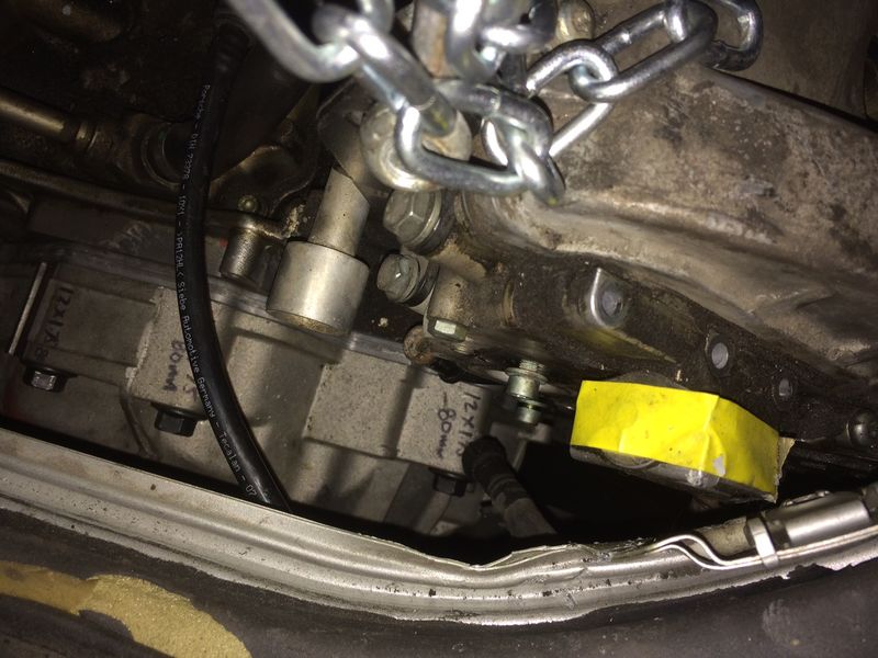
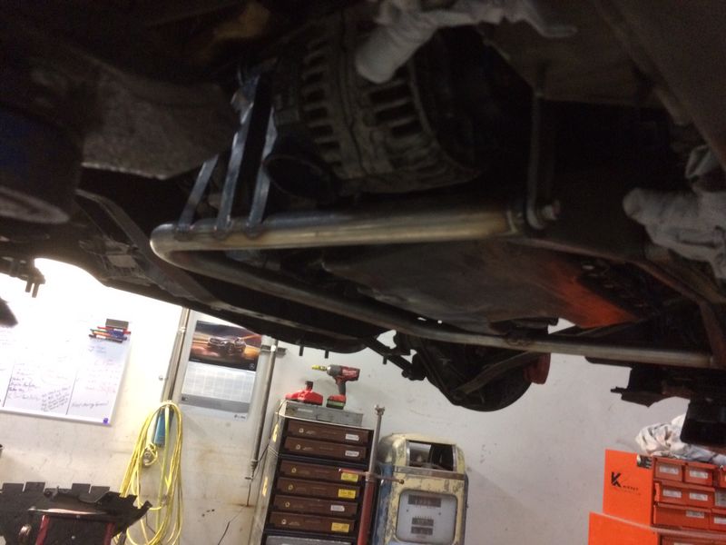
More progress, modified the 987 trans to accept the crank position sensor for the Audi V8.
|
|
|
|
|
02-27-2018, 06:12 PM
|
#107
|
|
Registered User
Join Date: Oct 2017
Location: Portland OR
Posts: 100
|
|
|
|
|
|
02-27-2018, 06:14 PM
|
#108
|
|
Registered User
Join Date: Oct 2017
Location: Portland OR
Posts: 100
|
|
|
|
|
|
02-27-2018, 06:18 PM
|
#109
|
|
Registered User
Join Date: Oct 2017
Location: Portland OR
Posts: 100
|
|
|
|
|
|
02-27-2018, 06:27 PM
|
#110
|
|
Registered User
Join Date: Oct 2017
Location: Portland OR
Posts: 100
|
Cradle is getting powder coated, I will post pics when it come back. I'm ready to take orders if anyone is serious about getting one of these. Make sure you are okay with the way the motor fits...I'm still looking for a convenient way to make the TB connect to an air filter. It will be easy with my race car, not sure how to make it work with the OEM engine compartment. Any one know if ABZ 32 valve intake will bolt on the 40 valve motor? The TB seems quite a bit lower on the ABZ motor and might clear with just tipping it down in the rear...
|
|
|
|
|
02-27-2018, 06:38 PM
|
#111
|
|
Registered User
Join Date: Jun 2014
Location: LB, Germany
Posts: 1,526
|
Hi,
nice project.
Have a question: how much will be the offset of the drive shaft at the gearbox compared to the stock configuration? Or won't there be any offset?
Regards
|
|
|
|
|
02-27-2018, 07:17 PM
|
#112
|
|
Registered User
Join Date: Oct 2017
Location: Portland OR
Posts: 100
|
Maintains the OEM transmission location so no change in the axle angles.
|
|
|
|
|
02-28-2018, 10:51 AM
|
#113
|
|
Registered User
Join Date: Oct 2015
Location: Cardiff, UK
Posts: 107
|
That's the engine you should be fitting 

|
|
|
|
|
02-28-2018, 11:00 AM
|
#114
|
|
Registered User
Join Date: Oct 2017
Location: Portland OR
Posts: 100
|
Quote:
Originally Posted by Escy
That's the engine you should be fitting
|
It's up next...turbo packaging in stock location is bad. Wish there was a way to just pop it in and use the Audi routing for the turbo, nice and clean, just in the wrong places to clear the engine bay.
|
|
|
|
|
02-28-2018, 02:03 PM
|
#115
|
|
Registered User
Join Date: Oct 2015
Location: Cardiff, UK
Posts: 107
|
I'm interested to see how you go about doing the 2.7t
|
|
|
|
|
03-01-2018, 05:44 AM
|
#116
|
|
Registered User
Join Date: Aug 2015
Location: Waterloo, Ontario
Posts: 193
|
I was just in the garage measuring the 4.2L yesterday to see how it would fit in the engine bay of the Boxster. I got a little scared. So it's nice to see these pics Dave!
I'm curious though, in what way to do you plan on cutting up the engine cover?
Also, Tom, on the subject of the 2.7t swap. The way I looked at it was if you have to fabricate the turbo manifolds/up-pipes, exhaust, and everything else that makes the 2.7t different from a normal 2.8L V6... then why wouldn't you just swap in the engine with 2 extra cylinders to begin with. A turbo V8 Boxster is way cooler than a turbo V6 Boxster... just saying 
Last edited by B6T; 03-01-2018 at 05:48 AM.
|
|
|
|
|
03-01-2018, 05:47 AM
|
#117
|
|
Registered User
Join Date: Aug 2015
Location: Waterloo, Ontario
Posts: 193
|
Quote:
Originally Posted by titaniumdave
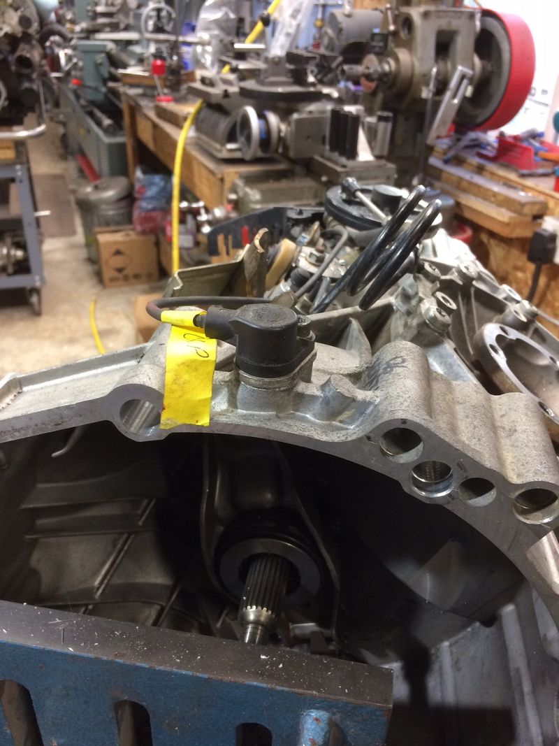
More progress, modified the 987 trans to accept the crank position sensor for the Audi V8.
|
Hey Dave,
That metal piece under the crank angle sensor is actually a spacer. It is used depending on whether you have an auto engine or manual engine. I can't remember which is which, but if memory serves I believe I had to remove it when I swapped an automatic 2.7t into my manual B6 A4.
Otherwise the crank sensor may not read and you'll be chasing no-start issues for weeks and probably end-up pushing the car off a cliff.
|
|
|
|
|
03-01-2018, 08:21 AM
|
#118
|
|
Registered User
Join Date: Oct 2017
Location: Portland OR
Posts: 100
|
Quote:
Originally Posted by B6T
Hey Dave,
Otherwise the crank sensor may not read and you'll be chasing no-start issues for weeks and probably end-up pushing the car off a cliff.
|
Yes, I just stuffed the whole part in the hole for a place keeper. I do not have the clutch worked out yet, the Valeo 2.7/4.2L is close but I need a 3mm spacer behind the flywheel to get the starter ring in the correct location AND the whole set up seems to be too close to the throw out bearing even with the motor/trans spacer ring. This gets worse with the 3mm spacer so the solution may be to make the flywheel thinner by 5-8mm depending on how it all measures. An easy but time consuming job on the mill. Keeps the tone ring in the correct position as well as dropping 2-3LB. off a very heavy clutch and makes it so I can swap discs and pressure plates in future rebuilds with off the shelf parts.
Once the clutch is worked out, then the depth of the sensor will be obvious. Looks like you are correct about not needing the spacer, I agree.
|
|
|
|
|
03-01-2018, 08:37 AM
|
#119
|
|
Registered User
Join Date: Oct 2017
Location: Portland OR
Posts: 100
|
Quote:
Originally Posted by B6T
I'm curious though, in what way to do you plan on cutting up the engine cover?
Also, Tom, on the subject of the 2.7t swap. The way I looked at it was if you have to fabricate the turbo manifolds/up-pipes, exhaust, and everything else that makes the 2.7t different from a normal 2.8L V6... then why wouldn't you just swap in the engine with 2 extra cylinders to begin with. A turbo V8 Boxster is way cooler than a turbo V6 Boxster... just saying |
2 thoughts here, the final cradle for this style of installation will be another 25mm lower on the front. I realize with the steel cross suspension support in place, the oil pan is well above the line the cross member defines. This will help get more front head/belt cover clearance. I think this will fit with just some hammer massaging of the front engine cover areas. It will also help move the TB away from the cover in the back where the middle tab will need to be cut off. I am looking at the intake to see if I can machine the TB flange at an angle, tipping the TB down and moving it forward at the same time. This works fine for my race car since the EGR system will be deleted/re-routed into a catch can. Not sure how this will work out with a street car but there appears to be plenty of points where the EGR system can pull vacuum to make the ECU happy.
As far as the V6 goes, my buddy who is helping likes turbo set ups because they can make lots of torque. We both come from the NSX world where everything is V6 since you can't stuff more cylinders in the NSX engine hole with out putting the motor longitudinal rather than transverse.
Once this car is running, I will start on a new cradle that will work for the V6 and maybe LS V8 options for those who really want to break transmissions...it will have this style cradle replacing the rear steel suspension brace:
https://www.engineswapdepot.com/?p=11960
|
|
|
|
|
03-01-2018, 02:05 PM
|
#120
|
|
Registered User
Join Date: Oct 2015
Location: Cardiff, UK
Posts: 107
|
Quote:
Originally Posted by B6T
Also, Tom, on the subject of the 2.7t swap. The way I looked at it was if you have to fabricate the turbo manifolds/up-pipes, exhaust, and everything else that makes the 2.7t different from a normal 2.8L V6... then why wouldn't you just swap in the engine with 2 extra cylinders to begin with. A turbo V8 Boxster is way cooler than a turbo V6 Boxster... just saying |
Yeah, that thought crossed my mind. The way I approached my first 2.7t build, I could have put a turbo V8 in there. I don't think a naturally aspirated V8 with a turbo kit would do the numbers I wanted out of the V6 (was looking for 600bhp) without the bottom end being built and the RS6 V8's are expensive.
The other thing that puts me off the V8 is they always seem to end up being a bit of hack job when it comes to the intake and throttle body. Fabricating an inlet manifold seems to be the only tidy way around it.
I'm building another 2.7t and plan on keeping the turbos in the standard location this time.
|
|
|
|
 Posting Rules
|
You may not post new threads
You may not post replies
You may not post attachments
You may not edit your posts
HTML code is On
|
|
|
All times are GMT -8. The time now is 08:40 PM.
| |


 Linear Mode


