 06-13-2012, 11:53 AM
|
#21
|
|
Registered User
Join Date: Oct 2010
Location: US, Calif
Posts: 72
|
To JFP in PA: I too am installing my IMS bearing via the Pelican article and have the sprocket locked with three set screws. Two tensioners are removed as well per the Pelican article. My IMS is also cocked a bit in the case hole.
Now I'm concerned after reading your response below... I currently have a new (pelican) bearing stuck half way in the IMS and hopefully will be pulling it back out when LN sends a hexagon shaft tool to fit the new bearing shaft (ordered it yesterday)... Once/if I get the bearing out is it possible to put tensioners back in (or not) and rotate to TDC? I don't think I want any movement here but need to ask. If this isn't possible then I'm going to make a lock that fits to the engine case and one or two of the bolts on the flywheel flange.
Too bad the LN and Pelican procedures are so different. Seems it can really get us hobbyist in hot water. Appreciate any info you wish to share on my issue. It appears others have been in similar positions. Thank you, Rgs, John mickymingjh@gmail.com
|

|

|
|
06-13-2012, 12:00 PM
|
#22
|
|
Registered User
Join Date: Jul 2011
Location: Richmond, VA (The Fan)
Posts: 978
|
Quote:
Originally Posted by 2000boxster986

To JFP in PA: I too am installing my IMS bearing via the Pelican article and have the sprocket locked with three set screws. Two tensioners are removed as well per the Pelican article. My IMS is also cocked a bit in the case hole.
Now I'm concerned after reading your response below... I currently have a new (pelican) bearing stuck half way in the IMS and hopefully will be pulling it back out when LN sends a hexagon shaft tool to fit the new bearing shaft (ordered it yesterday)... Once/if I get the bearing out is it possible to put tensioners back in (or not) and rotate to TDC? I don't think I want any movement here but need to ask. If this isn't possible then I'm going to make a lock that fits to the engine case and one or two of the bolts on the flywheel flange.
Too bad the LN and Pelican procedures are so different. Seems it can really get us hobbyist in hot water. Appreciate any info you wish to share on my issue. It appears others have been in similar positions. Thank you, Rgs, John mickymingjh@gmail.com |
I got around this by grinding an angle into the ims pulling tool so the bearing would funnel into the cylinder. The funnel straightened the bearing as I pulled it out and once it was most of the way into the removal tool I inserted the set screws. I used an angle grinder to grind the angle into the tool and it turned out pretty precise(for an angle grinder). If your nervous to grind your but want to give it a shot I can send you mine.
I agree with you, it is unfortunate that the LN and pelican procedures are different.
__________________
1997 Boxster 4.2L Audi V8 Bi-Turbo
2003 911 C2
NASA HPDE Instructor
Last edited by truegearhead; 06-13-2012 at 12:29 PM.
|
|
|
|
|
06-13-2012, 01:54 PM
|
#23
|
|
Registered User
Join Date: Feb 2005
Location: It's a kind of magic.....
Posts: 6,660
|
Quote:
Originally Posted by 2000boxster986
To JFP in PA: I too am installing my IMS bearing via the Pelican article and have the sprocket locked with three set screws. Two tensioners are removed as well per the Pelican article. My IMS is also cocked a bit in the case hole.
Now I'm concerned after reading your response below... I currently have a new (pelican) bearing stuck half way in the IMS and hopefully will be pulling it back out when LN sends a hexagon shaft tool to fit the new bearing shaft (ordered it yesterday)... Once/if I get the bearing out is it possible to put tensioners back in (or not) and rotate to TDC? I don't think I want any movement here but need to ask. If this isn't possible then I'm going to make a lock that fits to the engine case and one or two of the bolts on the flywheel flange.
Too bad the LN and Pelican procedures are so different. Seems it can really get us hobbyist in hot water. Appreciate any info you wish to share on my issue. It appears others have been in similar positions. Thank you, Rgs, John mickymingjh@gmail.com |
There are several large issues here, some involving the board owners, so I will try to tread lightly in deference to that.
I do not like the three set screw method for exactly the reason I stated; the rear gear on the intermediate shaft is an interference press fit. Pushing on it with threaded devices is asking for trouble. If you dislodge the gear even a little bit by pushing on it with set screws, the rear cam chains will be moved off axis towards the case, which is not a good thing as there is no known way to correct this without total disassembly of the engine. Worse yet, using the set screws at all is completely unnecessary if you had followed the LN procedures that Jake Raby developed in conjunction with Charles Navarro. Their procedure is slightly more complicated, but it goes smoothly every time.
The reason your shaft is off center is because the remaining tensioner is still loading it, which pulls it to one side. From your question, I have to assume that you are not currently at TDC, and are also not using the cam holding tools. If that is the case, I would not try to reinstall the tensioners you removed and then rotate the crank as the odds are very poor on getting away with that while there is no flange holding the rear of the IMS shaft bearing. Removing the third tensioner might be a better way to get it centered up so you can reassemble everything, but there is also no guarantee on the outcome of that approach.
I really hate to sound so negative about these procedures, but unfortunately like most things in life, there is usually one way to do something without encountering issues, and a whole bunch of short cut methods to do it that dont always work out as intended. Some have had good luck using methodology different from LNs procedures, but not all have been so fortunate, and some have ended up being outright disastrous.
__________________
Anything really new is invented only in ones youth. Later, one becomes more experienced, more famous and more stupid. - Albert Einstein
|

|
|
|
06-13-2012, 03:25 PM
|
#24
|
|
Registered User
Join Date: Oct 2010
Location: US, Calif
Posts: 72
|
Hi Truegearhead. Thank you for the offer. If you have a pic that would be perfect. My removal tool does have a bevel inside to help guide the bearing so I'm thinking this might be what you're referring to, if not a pic would sure be appreciated.
JFP, Thank you, I copy!
The sad part is this; I had TDC locked to begin with (before I stated with the old bearing pull) then I read and re-read the Pelican article and thought I was doing something wrong... so, I switched methods and locked the sprocket once all three holes showed showed some sprocket meat. I figured this method was to prevent having a chain slip at the IMS sprocket so it made sense to lock the sprocket. Now knowing the sprocket is press fit concerns me. The set screws are just hand tight, no more. What further concerns me is the new bearing I now have stuck on the damn IMS. Hopefully the LNE tool will arrive soon so I can get that off and attempt a re-install providing I didn't damage anything. So next would be install the bearing correctly and then try to get the cover back on. So I may have to release the third tensioner to get the IMS to move back to center. I'll try that.
I realize I've followed a procedure here that was supposed to work but it appears to have some issues. Granted more research would have been a good idea... but that didn't happen and now it may backfire, I hope not! I appreciate your expertise and response. Cheers, John
|
|
|
|
|
06-13-2012, 03:56 PM
|
#25
|
|
Registered User
Join Date: Feb 2005
Location: It's a kind of magic.....
Posts: 6,660
|
Don't beat yourself up over this; you are not the only one to have encountered problems using this method. Now move cautiously and deliberately to try and get the install back on track.
__________________
Anything really new is invented only in ones youth. Later, one becomes more experienced, more famous and more stupid. - Albert Einstein
|
|
|
|
|
06-13-2012, 04:35 PM
|
#26
|
|
Registered User
Join Date: Oct 2010
Location: US, Calif
Posts: 72
|
Thanks JFP, Agreed!
Cheers,
|
|
|
|
|
06-13-2012, 04:42 PM
|
#27
|
|
Registered User
Join Date: Oct 2011
Location: sac. ca
Posts: 156
|
John take some pics... a pic is worth a thousand words..
__________________
98 boxster
82 280sl parts for sale
|
|
|
|
|
06-13-2012, 04:46 PM
|
#28
|
|
Registered User
Join Date: Oct 2011
Location: sac. ca
Posts: 156
|
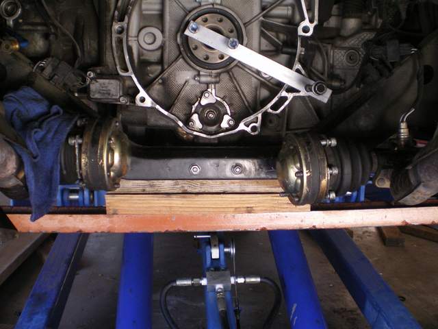
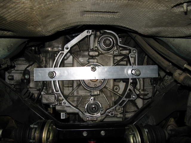
secure your crank like this before you release anything, are your cams locked?
__________________
98 boxster
82 280sl parts for sale
|
|
|
|
|
06-13-2012, 09:00 PM
|
#29
|
|
Registered User
Join Date: Oct 2010
Location: US, Calif
Posts: 72
|
Hi Tim, thanks, I just but a brace similar to yours on this afternoon. Cams are not locked. I'll post some pics here tomorrow of the bearing and brace. Btw, do you still have that extra pelican bearing? Mine may be damaged. I'm interested if you do. Tks Tim
|
|
|
|
|
06-13-2012, 09:18 PM
|
#30
|
|
Registered User
Join Date: Oct 2011
Location: sac. ca
Posts: 156
|
Hi John.
sent a PM
__________________
98 boxster
82 280sl parts for sale
|
|
|
|
|
06-14-2012, 04:34 AM
|
#31
|
|
Registered User
Join Date: Jul 2011
Location: Richmond, VA (The Fan)
Posts: 978
|
Quote:
Originally Posted by 2000boxster986
Hi Truegearhead. Thank you for the offer. If you have a pic that would be perfect. My removal tool does have a bevel inside to help guide the bearing so I'm thinking this might be what you're referring to, if not a pic would sure be appreciated.
JFP, Thank you, I copy!
The sad part is this; I had TDC locked to begin with (before I stated with the old bearing pull) then I read and re-read the Pelican article and thought I was doing something wrong... so, I switched methods and locked the sprocket once all three holes showed showed some sprocket meat. I figured this method was to prevent having a chain slip at the IMS sprocket so it made sense to lock the sprocket. Now knowing the sprocket is press fit concerns me. The set screws are just hand tight, no more. What further concerns me is the new bearing I now have stuck on the damn IMS. Hopefully the LNE tool will arrive soon so I can get that off and attempt a re-install providing I didn't damage anything. So next would be install the bearing correctly and then try to get the cover back on. So I may have to release the third tensioner to get the IMS to move back to center. I'll try that.
I realize I've followed a procedure here that was supposed to work but it appears to have some issues. Granted more research would have been a good idea... but that didn't happen and now it may backfire, I hope not! I appreciate your expertise and response. Cheers, John
|
Mine had a bevel as well and I could feel the bearing pull into the bevel but then stop which is what gave me the idea to cut the sharp angle into the puller. I'll send a pic when I'm able to get back to the garage
__________________
1997 Boxster 4.2L Audi V8 Bi-Turbo
2003 911 C2
NASA HPDE Instructor
|
|
|
|
|
06-14-2012, 07:01 AM
|
#32
|
|
Registered User
Join Date: Oct 2010
Location: US, Calif
Posts: 72
|
Pics
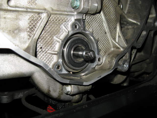
Here's the pic of the issue with the bearing. It didn't take much to get it off kilter... It won't move at all. I can rotate the shaft and feel the bearings track so it's under some pressure (or I damaged it). The brace is very similar to what Feelyx used.
Thank you guys for sharing my pain. I'm sure it will be fine as soon as I get that pesky bearing back out.
|
|
|
|
|
06-14-2012, 07:31 AM
|
#33
|
|
Registered User
Join Date: Oct 2011
Location: sac. ca
Posts: 156
|
Which tensioners do you have out? also do ou have the broken shaft extractor from the ln kit?
__________________
98 boxster
82 280sl parts for sale
|
|
|
|
|
06-14-2012, 08:44 AM
|
#34
|
|
Track rat
Join Date: Nov 2006
Location: Southern ID
Posts: 3,701
|
Yikes! Maybe time to update the Pelican IMS procedure article and include critical information like locking at TDC and locking the cams?? Pelican IMS DIY Reloaded 
__________________
2009 Cayman 2.9L PDK (with a few tweaks)
PCA-GPX Chief Driving Instructor-Ret.
|
|
|
|
|
06-14-2012, 09:18 AM
|
#35
|
|
Registered User
Join Date: Oct 2008
Location: O.C. CA
Posts: 3,709
|
FYI Pelican Parts Info 1-888-280-7799
|
|
|
|
|
06-14-2012, 10:57 AM
|
#36
|
|
Registered User
Join Date: Oct 2010
Location: US, Calif
Posts: 72
|
Hi Tim, the rear tensioners are out I have not yet removed the front one. I do have the 'broken shaft' extractor from the kit but it did not fit on the new bearing shaft. When talking to LNE they advised they just now put the new hex extractor for new bearings (with larger shafts) up for sale so I should have that in hand today or tomorrow. Then hopefully just a matter of using the LNE bearing puller to pull the bearing out, then clean out the shaft again and check the bearing to see if it's damaged. If I still feel the bumping in the bearing I'm going to get another one. If not, then back to the freezer with it and try it all over again.
Seems like using the regular bearing puller would be the best way to go but I'm open to any ideas anyone has to get past this issue. Thanks, John
|
|
|
|
|
06-14-2012, 11:37 AM
|
#37
|
|
Registered User
Join Date: Jul 2011
Location: Richmond, VA (The Fan)
Posts: 978
|
This job really can be a nightmare!
There are so many things that can go wrong
Broken exhaust manifold bolts
Broken IMS shaft
Bearing off center
Timing slips
Jamming the bearing halfway in during installation
etc.
__________________
1997 Boxster 4.2L Audi V8 Bi-Turbo
2003 911 C2
NASA HPDE Instructor
|
|
|
|
|
06-14-2012, 12:20 PM
|
#38
|
|
Registered User
Join Date: Oct 2011
Location: sac. ca
Posts: 156
|
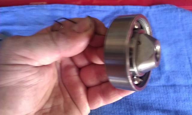
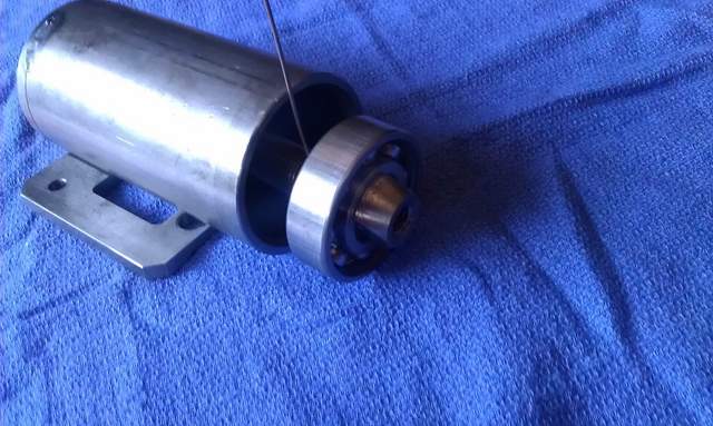
John, you can use the extractor by knocking out the shaft, and inserting the allen screw they included in the kit. I will get a pic up for you in a minute
__________________
98 boxster
82 280sl parts for sale
|
|
|
|
|
06-14-2012, 12:35 PM
|
#39
|
|
Registered User
Join Date: Oct 2011
Location: sac. ca
Posts: 156
|
__________________
98 boxster
82 280sl parts for sale
|
|
|
|
|
06-14-2012, 02:19 PM
|
#40
|
|
Registered User
Join Date: Oct 2010
Location: US, Calif
Posts: 72
|
Hi Tim, Ghezzz... Now I see how it works.... Silly me  I was thinking the easy out tool worked a bit differently but now it all makes good sense. I'll go stand in the corner for an hour on time out.... Thank you for the photos. If the other tool doesn't get here by tomorrow I'll see about tapping the center shaft out of the bearing and using the easy out. Thanks Tim, you always come to the rescue.
|
|
|
|
 Posting Rules
|
You may not post new threads
You may not post replies
You may not post attachments
You may not edit your posts
HTML code is On
|
|
|
All times are GMT -8. The time now is 07:30 PM.
| |


 Boxster
 Lil Red
 2009 Porsche Cayman 2.9L
 Mean Motor Scooter
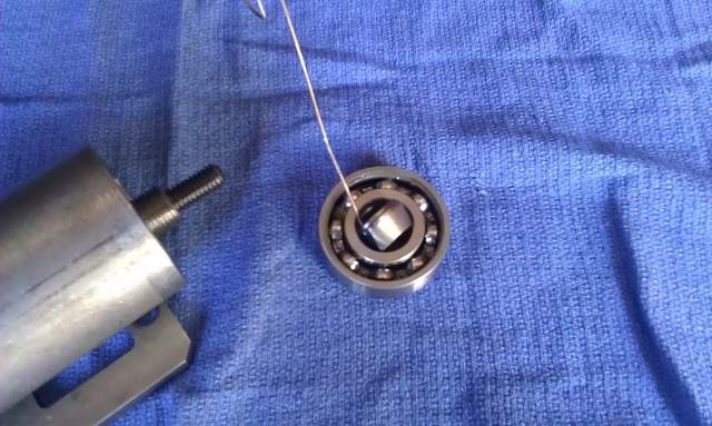
 Linear Mode


