 11-22-2013, 07:31 PM
|
#1
|
|
Beginner
Join Date: Mar 2013
Location: Houston
Posts: 1,659
|
Engine Removal, Rebuild, and Re-installaion
This is going to be a real time thread so it will be slow when progress is slow, or more to the point, when I am. I am not a mechanic, I'm an engineer. That may make this whole process a whole lot more entertaining to watch. Comments are welcome from all corners as that's part of the fun. Just know I give as good as I get, maybe better. Here is my favorite picture of my boxster. I did not post it on the my favorite picture string because I'b be mistaken for a troll, well maybe not mistaken.
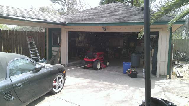
Oh yeah, that's my new tractor pulling the Box, a 1979 8 speed Wheel Horse with 14hp cast iron Kohler. It was a uniform shade of rust when I bought it - nice ride.
|

|

|
|
11-22-2013, 07:40 PM
|
#2
|
|
Beginner
Join Date: Mar 2013
Location: Houston
Posts: 1,659
|
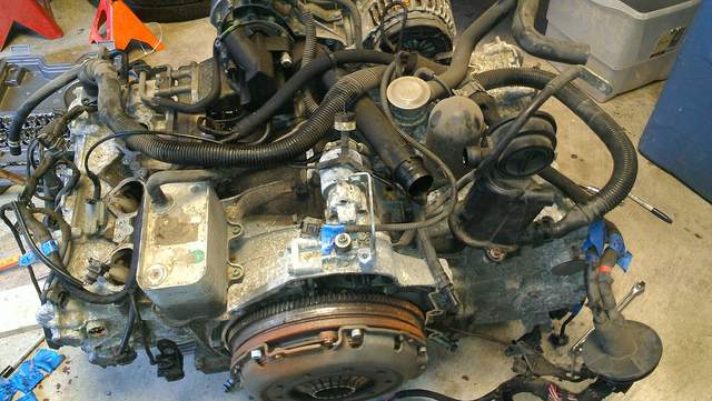
To get the motor out I used to 101 Porsche Projects book. I highly recommend purchasing this if you are reading this string. 101 Projects step by step directions. It also has pictures for each step so I refer you to that text for pictures. Here is the engine out of the car

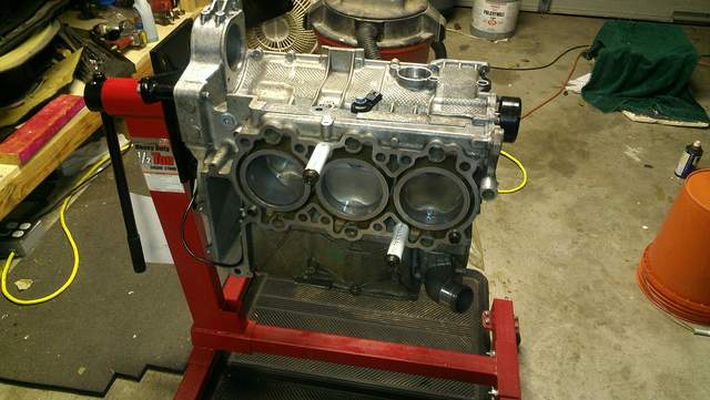
This is one of many photos I took of the engine. Walk around the engine taking photos at about every 45 degrees, from a distance and then close up. you can not take enough pictures. I have tons, and as I peruse them I realize I don't have enough.
|
|
|
|
|
11-22-2013, 07:54 PM
|
#3
|
|
Beginner
Join Date: Mar 2013
Location: Houston
Posts: 1,659
|
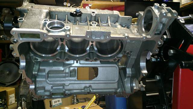
So here is an interesting picture. I decided to label everything with blue tape and a sharpie. I used this everywhere - a blue tape flag and a description of what it is - that made me go find out what everything was as I disassembled. I'm thinking that will help with re-assembly. I also used this with as many bolts as practical keeping the bolts taped to the holes in the component they came out of. Also as many of the loose parts and associated bolts are in their own labeled gallon ziplock bags as possible. Also, note the AOS is failing, plenty of oil in the intake. Apparently there was no white smoke, but look at the oil on the manifold between the alternator and AC compressor mounting location near the power steering pump.
Last edited by Jamesp; 11-22-2013 at 07:56 PM.
Reason: accuracy
|
|
|
|
|
11-22-2013, 08:27 PM
|
#4
|
|
Beginner
Join Date: Mar 2013
Location: Houston
Posts: 1,659
|
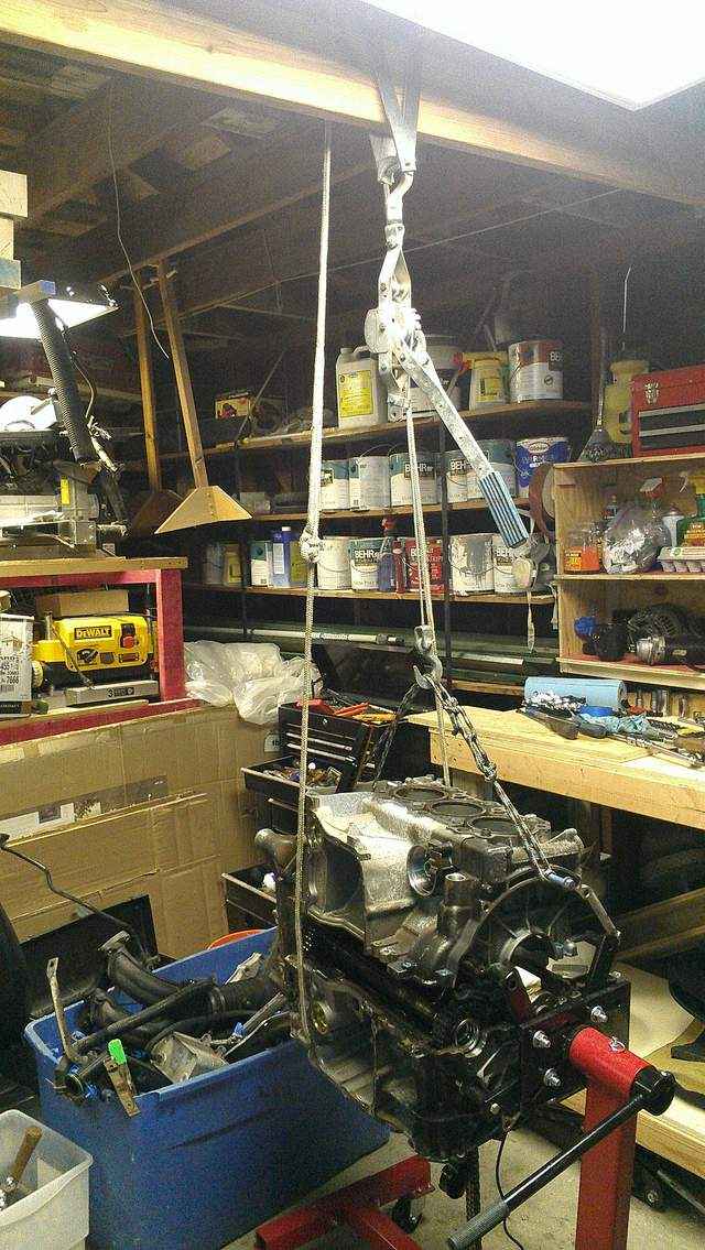
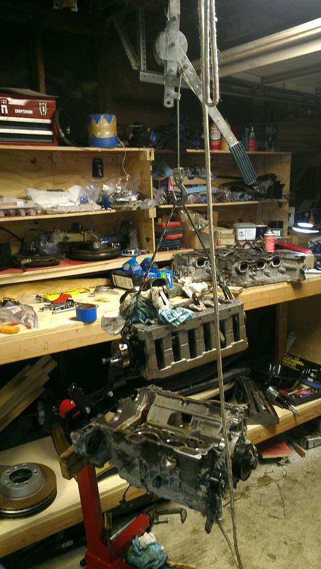
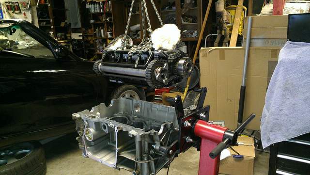
Note the overhead crane at the top of the photo. It is a 2X8 hung from the rafters at 90 degrees to them. There is a steel "A" frame hanging upside down with wheels on the legs of the "A" running on the top of the 2X8. A come along completes the set up and allows one person to slowly and carefully remove the split case halves, and remove the crankshaft and bearing block with a minimum of drama.
|
|
|
|
|
11-23-2013, 12:24 AM
|
#5
|
|
Custom User Title Here
Join Date: Mar 2012
Location: Ft. Leonard Wood
Posts: 6,169
|
Good show! 
I'll be watching this closely. Thanks for sharing! 
(Don't be stingy with all those pics you're taking)
__________________
https://youtube.com/@UnwindTimeVintageWatchMuseum
|
|
|
|
|
11-23-2013, 05:33 AM
|
#6
|
|
Beginner
Join Date: Mar 2013
Location: Houston
Posts: 1,659
|
Though the lower end looked almost new when it was opened up (including what appeared to be machining chips), due to mileage, and the failing AOS, there was plenty of oily carbon built up on the pistons. Cleaning it was a challenge. Various hydrocarbon solvents (Chem tool, carb cleaner, brake cleaner, lacquer thinner, etc.) were tried with limited success, the best success came with Chem tool. After doing a load of research a two step process seemed easiest. Buy an empty paint can and soak the piston in Chem tool overnight. After a little scrubbing with a plastic brush only a thin tan build up was left, which turned out to be water soluble. Scrubbing that with a hydrocarbon thinner has very little effect. Some soap and water (wrist pin and rings removed) with a little baking soda cleaned it right up. Rinse the heck out of the bare piston in hot water, dry completely with a lint free towel, Make sure water is out of every crack and crevice. Hit it with WD 40 just to be sure no water is left behind, then soak it with Mobil 1. Or the pistons could just be sent out for cleaning, but where's the fun in that?

|
|
|
|
|
11-23-2013, 07:56 AM
|
#7
|
|
Engine Surgeon
Join Date: Aug 2008
Location: Cleveland GA USA
Posts: 2,425
|
B12 is by far the best for this outside of an ultrasonic cleaner..
Meaure those cylinders with a dial bore gauge from different axis and at 3 points top to bottom and look for taper and out of roundness. Guilty until proven innocent!
__________________
Jake Raby/www.flat6innovations.com
IMS Solution/ Faultless Tool Inventor
US Patent 8,992,089 &
US Patent 9,416,697
Developer of The IMS Retrofit Procedure- M96/ M97 Specialist
|
|
|
|
|
11-23-2013, 11:16 AM
|
#8
|
|
Beginner
Join Date: Mar 2013
Location: Houston
Posts: 1,659
|
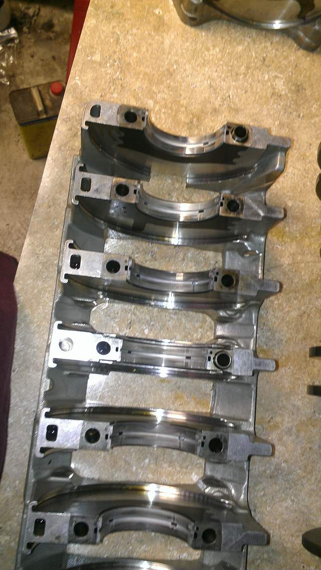
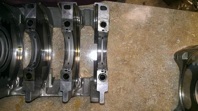
Another tool to buy! One of the perks of doing anything yourself. Looks like a dial bore gauge will join the collection. Having the gear carrier and crankshaft out of the car its time to replace the main and thrust bearings. This engine was a daily driver, mainly freeway with 120K miles. The previous owner drove semi aggressively in Houston traffic and was a stickler for oil changes with the Porsche dealer. As the pictures show, the mains were shot with the babbitt missing in some spots and the backer worn clean through to the steel on at least one edge. The crankshaft mains were not scored and actually looked great so they got a light polish. My takeaway from this is the recommended lube results in worn out main bearings at 120K for a car driven mainly in top gear. The rod bearings, though not as worn as the mains, were also replaced.
|
|
|
|
|
11-24-2013, 05:58 PM
|
#9
|
|
Beginner
Join Date: Mar 2013
Location: Houston
Posts: 1,659
|
The IMS bearing failed on this engine. Using this and other forums, the cause of bearing failure appears to be related to loss of lubrication. The root cause of the lubrication loss appears to be due to differential pressure created by the IMS tube heating and cooling pumping engine oil through the IMS bearing. Venting the IMS tube eliminates this, and should allow the grease sealed in the IMS bearing to remain with the bearing. The "new" used IMS shaft is from Ebay, and the original bearing with buna-n seals was replaced with a Nachi 6204 2NSE sporting full contact Viton seals. The bolt is from the Pelican Parts kit. A vent hole can be seen drilled between the teeth of the camshaft drive sprocket. Another is drilled in the same place 180 degrees out from the first hole. 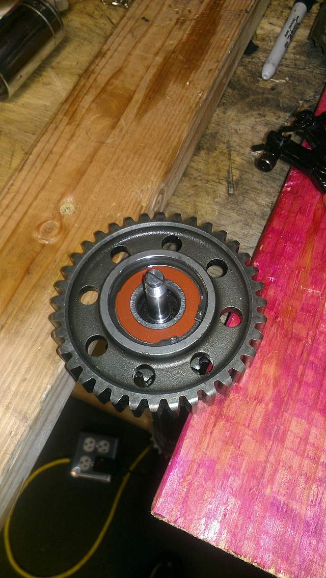
|
|
|
|
|
11-25-2013, 03:10 PM
|
#10
|
|
Registered User
Join Date: Feb 2013
Location: Land of naught
Posts: 1,302
|
Great thread- thanks for sharing. Is the replacement bearing a 'standard' bearing in all other ways and is it a single-row? Did the tractor really pull the car?
__________________
Death is certain, life is not.
|
|
|
|
|
11-25-2013, 04:22 PM
|
#11
|
|
Beginner
Join Date: Mar 2013
Location: Houston
Posts: 1,659
|
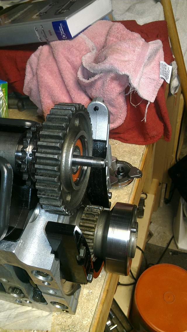
The replacement bearing is similar to the original bearing. Both are 6204 sealed bearings. "6204" is bearing speak for a single row deep groove ball bearing of a certain size. After that there are other things to consider. The original bearing appeared to be a 6204 "N", or "0", meaning a standard clearance bearing. The bearing code was partially outdated so decoding it took some guesswork. It was also sealed on both sides, but interestingly enough, reading the bearing number embossed on the side seals, it should have been sealed on only one side. Life's little mysteries. The seals (more choices) were Buna n full contact seals. Buna n itself comes with different material properties depending on the blend used to make it. The replacement bearing is a 6204 C3 which means it should have more clearance than an "N". The C3 clearance is used in high temperature environments to maintain clearance under thermal distortion. This bearing was also being marketed as a high temp bearing, so the grease inside should hold up to higher temperatures along with the Viton seals. The tractor can pull a plow, the car was no problem. So tonight new timing chains, a new timing chain guide rail, and a new timing chain pad were installed. :dance:


Last edited by Jamesp; 11-25-2013 at 04:27 PM.
Reason: clarification
|
|
|
|
|
11-26-2013, 03:27 PM
|
#12
|
|
Registered User
Join Date: Feb 2013
Location: Land of naught
Posts: 1,302
|
Wow those chains look HD compared to what I've seen in other engines.
__________________
Death is certain, life is not.
|
|
|
|
|
11-27-2013, 10:09 PM
|
#13
|
|
Registered User
Join Date: Jun 2013
Location: Virginia
Posts: 353
|
Wow, badass.. you have a lot of guts. Great thread!
__________________
:ah:
|
|
|
|
|
11-28-2013, 05:18 AM
|
#14
|
|
Registered User
Join Date: Dec 2010
Location: Eastern canada
Posts: 262
|
Wow, brings back memories,.... neat car eh!
You were lucky to find a used IMS in good shape. If you put the vent holes in did you also pin the gears to the shaft?
I see your old IMS on the lower shelf, can it be salvaged? I was lucky, LN was able to salvage mine.
Is that the original IMS to Crank chain tensioner? Did any of your chain guides or tensioners fail?
The first Pic is a keeper. Maybe the Admin. would consider it as the opening Pic for this DIY Project guide! Its great.
|
|
|
|
|
11-28-2013, 06:23 AM
|
#15
|
|
Beginner
Join Date: Mar 2013
Location: Houston
Posts: 1,659
|
This is a 3 chain engine which may be why the chains look HD, the IMS to crank was redesigned to a gear type chain instead of sprocket type in the 3 chain engines. Finding an IMS took forever, and then 2 in one week on Ebay. I've seen several others since, but none with a gear drive. I considered pinning the shaft, but weighing the risk benefit (loose pins in the engine) and my novice status as a machinist, I'm staying away from that. The old IMS shaft took it on the chin and now has 0.015 wobble in the gear. It's dead. Maybe I can stand it up with a base under it and make it into a trophy. That is the original tensioner arm. The IMS gave up the ghost at idle there was only one chip out of the plastic on a tensioner that looked related to the failure. There were metal chips embedded in all the tensioners. They will all be replaced. And I'd be honored to have admin use that first pic as an intro! 
|
|
|
|
|
12-09-2013, 05:01 PM
|
#16
|
|
Beginner
Join Date: Mar 2013
Location: Houston
Posts: 1,659
|
|
|
|
|
|
12-23-2013, 12:08 PM
|
#17
|
|
Beginner
Join Date: Mar 2013
Location: Houston
Posts: 1,659
|
Finally got a few hours free to make a little more progress.
On to pistons 1,2,3, so I'm taking credit for "making" this tool too, since I wrapped painters tape around a 3 inch extension and snapped the rest together- it worked great!
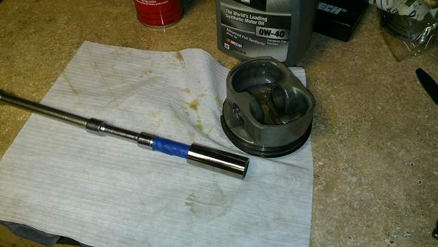
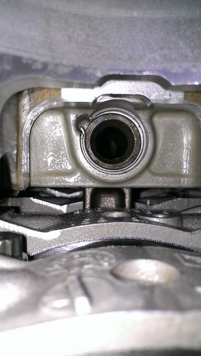
Instead of using a mirror to check the piston wrist pin clip, I put my cell phone in the adjacent cylinder and snapped a picture.
next the head and valve train goes on:
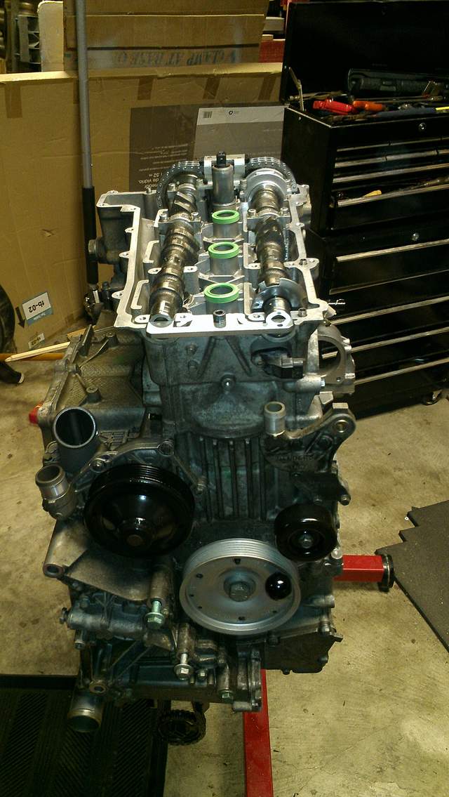
I finally understand the valve timing. Took me long enough.
Then the valve cover
More to come 
Last edited by Jamesp; 12-23-2013 at 12:11 PM.
|
|
|
|
|
12-25-2013, 10:33 PM
|
#18
|
|
Registered User
Join Date: Jun 2013
Location: Virginia
Posts: 353
|
Love the pics, great progress!
__________________
:ah:
|
|
|
|
|
12-26-2013, 09:06 AM
|
#19
|
|
Registered User
Join Date: Dec 2013
Posts: 1
|
Progress?
Your project looks good (just saw your 12/23 post)!
I have a 2001 Boxster S with IMS failure ... trying to figure out what I should do!
Thanks for all of the pictures and information.
Last edited by dbergondy; 12-26-2013 at 09:08 AM.
|
|
|
|
|
12-26-2013, 02:44 PM
|
#20
|
|
Registered User
Join Date: Feb 2013
Location: Land of naught
Posts: 1,302
|
I too am enjoying the great pics!
__________________
Death is certain, life is not.
|
|
|
|
 Posting Rules
|
You may not post new threads
You may not post replies
You may not post attachments
You may not edit your posts
HTML code is On
|
|
|
All times are GMT -8. The time now is 11:25 AM.
| |


 Linear Mode


