 11-24-2012, 11:22 AM
|
#21
|
|
Ex Esso kid
Join Date: Dec 2005
Location: NY
Posts: 1,605
|
Pwave, It looks so much better than stock it's dramatic! As for your comments on soldering, I've had to do it on a few boards before with only about a 50% success rate. Your caution should be well heeded, it's not like joining two wires. If you overheat it and some other solder on the board runs, that is truly where the new cusswords are created.
|

|

|
|
11-25-2012, 12:36 AM
|
#22
|
|
Registered User
Join Date: Aug 2010
Location: Germany
Posts: 97
|
Can't find the website
pwave, That dash looks awesome.
I would ask you to make one, but I've found that half the fun of the Box is learning new things. I've had some, but limited, experience with LED on PCB, so I think I'll tear apart a boom box or something to practice on. I looked for porscheleds.com, but get an error. Do you have an alternate address?
The sites I did find list voltage as 3.0-3.5VDC, but you said the CC is 1.5VDC. Am I looking at the correct LEDs, or will 3V ones work? These won't need a resistor, but the speedo/tach are 12V, so they will, correct?
Thanks for the supplies breakdown. Do you also have a breakdown for the rotary guages?
Last edited by Iflylow; 11-25-2012 at 12:43 AM.
|
|
|
|
|
11-25-2012, 08:37 AM
|
#23
|
|
Registered User
Join Date: Sep 2011
Location: Eureka, CA
Posts: 332
|
Quote:
Originally Posted by Iflylow

I looked for porscheleds.com, but get an error. Do you have an alternate address?
|
This is the same website everyone uses, they must have changed their name.
http://www.sportscarleds.com/
Last edited by Mrmaddbrad; 11-25-2012 at 08:40 AM.
|
|
|
|
|
11-25-2012, 11:01 AM
|
#24
|
|
Custom User Title Here
Join Date: Mar 2012
Location: Ft. Leonard Wood
Posts: 6,169
|
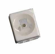
I recommend these LEDs.
They are rated at 3v-3.4v, but are plenty bright on the 1.5v board supply, as can be seen in my pictures 
If you order the dash led kit from the link that Brad provided above(formerly porscheleds.com), they come with the resistor built in. If you decide to make your own you will need resistors. Likewise, any LED powered off of 12 V(Cigarette lighter, ashtray) will need a resistor. You can use an online LED resistor calculator to determine what resistance you need for each LED.
__________________
https://youtube.com/@UnwindTimeVintageWatchMuseum
Last edited by particlewave; 07-16-2013 at 12:41 PM.
|
|
|
|
|
06-03-2013, 01:13 PM
|
#25
|
|
Registered User
Join Date: May 2012
Location: Kalamazoo, MI
Posts: 149
|
Quote:
Originally Posted by particlewave
Side note; my brain is fried!  |
I just did my climate control and two of the switches. I now know what you mean about your brain being fried. I didn't think the replacements would be quite as frustratingly small as they are, but eventually you get a rhythm going and it's not that difficult. I tested each one with my DMM set to diode, putting the probes not on the LED itself or the new solder, but in the vias on the same tracer (to ensure new solder was in fact making contact with the LED and pad). I could also double check polarity this way. I'm proud to say I was 23 for 23. The switches also went without a hitch. Hopefully tonight I will get a chance to reinstall everything and see how it looks.
I had initially thought that if I were to do this project again I might order 5050 LED's, which are the what is originally on the board. In retrospect, they might be quite a bit more difficult to solder because of how much they overlap the pad.
I also found a "For Sale" sign in the discount bin at the grocery store and made the diffuser.
What did you end up doing for the cigarette lighter? I finally figured out how to get the bulb holder apart for it and I see a few that should work on superbrightleds.com. Is that the only oddball, and the others (besides the gauges) are the 0603's?
__________________
2000 986 S - "The Black Widow"
|
|
|
|
|
06-04-2013, 05:57 AM
|
#26
|
|
Registered User
Join Date: May 2012
Location: Kalamazoo, MI
Posts: 149
|
After hooking everything back up last night, I was disappointed. The entire display was very dim as well as the buttons. It was difficult to tell that the buttons were even on, but they were. If I turned on the heated mirrors or central lock, the display "dot" light up well, but the rest was not good. Perhaps you used these?
Unique Leds 0603 Surface Mount Led - Blue 380mcd Max
They are the same size, but 3-4 times brighter than the ones you linked to.
__________________
2000 986 S - "The Black Widow"
|
|
|
|
|
06-08-2013, 11:16 PM
|
#27
|
|
Custom User Title Here
Join Date: Mar 2012
Location: Ft. Leonard Wood
Posts: 6,169
|
I am very sorry...I did link the wrong ones. I used the 250-380mcd LEDs.
Yikes. My apologies. That's a lot of work to do twice, but at least they're cheap. I'll fix the link.
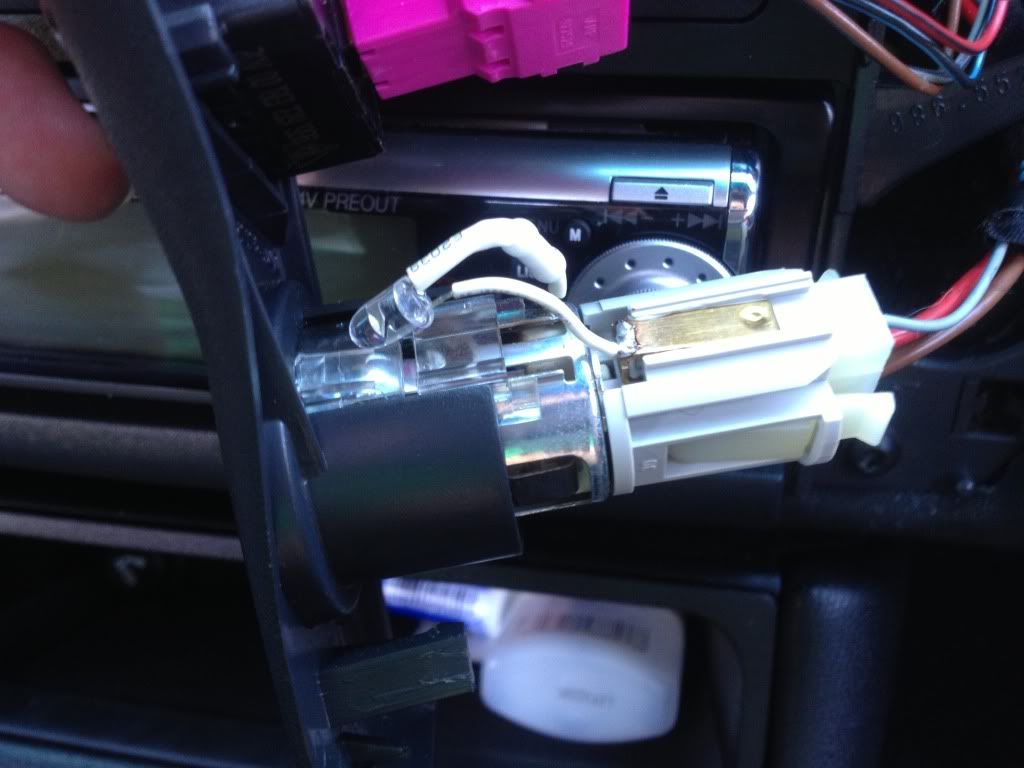
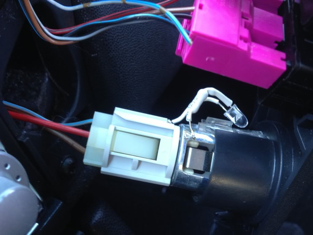
The headlight switch requires small standard(non-surface mount) LEDs as the are soldered to the rear of the board, not the surface. I had some in the parts bin that I used and don't have a part # for those, but any small 200-400mcd led would work. For the "ashtray" and lighter, I just picked up some full size LEDs from radio shack. On the lighter socket, I just removed all of the stock light hardware and directly soldered the negative leg of the led to the metal of the socket so that I could aim it at the diffuser and adjust it for optimum even light distribution. I'll see if I can get a picture soon.
__________________
https://youtube.com/@UnwindTimeVintageWatchMuseum
Last edited by particlewave; 06-08-2013 at 11:34 PM.
|
|
|
|
|
06-09-2013, 07:51 AM
|
#28
|
|
Registered User
Join Date: May 2012
Location: Kalamazoo, MI
Posts: 149
|
No worries, man. It took me less than an hour to do the first time and I'm actually an electronics engineer, so I've got all the right tools to do it. I wouldn't mind seeing the lighter socket setup you have.
__________________
2000 986 S - "The Black Widow"
|
|
|
|
|
06-10-2013, 02:53 PM
|
#29
|
|
Custom User Title Here
Join Date: Mar 2012
Location: Ft. Leonard Wood
Posts: 6,169
|
Here are some pictures of the lighter socket LED. I wasn't super happy with my approach here. I'm sure I could've designed something much better looking, but I figured that it wouldn't be seen anyway and this was an efficient way of mounting, powering, and aligning the LED for optimal light distribution in the diffuser ring. The resistor is on the negative leg under the heat shrink.
__________________
https://youtube.com/@UnwindTimeVintageWatchMuseum
|
|
|
|
|
06-21-2013, 08:35 PM
|
#30
|
|
Registered User
Join Date: May 2011
Location: United States
Posts: 11
|
Looks awesome
|
|
|
|
|
06-22-2013, 10:33 PM
|
#31
|
|
Custom User Title Here
Join Date: Mar 2012
Location: Ft. Leonard Wood
Posts: 6,169
|
Thanks Henkel
It's definitely better than orange and well worth the effort. 
__________________
https://youtube.com/@UnwindTimeVintageWatchMuseum
|
|
|
|
|
07-12-2013, 06:29 AM
|
#32
|
|
Registered User
Join Date: May 2012
Location: Kalamazoo, MI
Posts: 149
|
Any tips on getting to the LED on the intermittent wiper dial? I got the back off, but it looks like I would have to destroy the thing to get to the LED.
__________________
2000 986 S - "The Black Widow"
|
|
|
|
|
07-12-2013, 12:31 PM
|
#33
|
|
Custom User Title Here
Join Date: Mar 2012
Location: Ft. Leonard Wood
Posts: 6,169
|
Hmmm...I don't have one of those
__________________
https://youtube.com/@UnwindTimeVintageWatchMuseum
|
|
|
|
|
07-12-2013, 12:55 PM
|
#34
|
|
Registered User
Join Date: Feb 2012
Location: Toledo, OH
Posts: 58
|
You have me sold. I just got the kit for my dash from sportscarLEDs.com, the surface mount LEDs from the link you provided and a new climate control module from ebay.
Porsche Boxster, Carrera 996/997 LCD Replacement Repair Kit for Climate Control
Item# 200926743312
I needed just a LCD as mine leaked its liquid. But I found the whole module for $75 so now I have a test-bed for the soldering.
:dance:
|
|
|
|
|
07-16-2013, 01:24 AM
|
#35
|
|
Registered User
Join Date: Aug 2010
Location: Germany
Posts: 97
|
Quote:
Originally Posted by Benjamin
Any tips on getting to the LED on the intermittent wiper dial? I got the back off, but it looks like I would have to destroy the thing to get to the LED.
|
I just did mine a few weeks ago. You have to pry it off, but it does come apart and go back together again.
Sorry, no pics. I'm deployed again. someday I'll be able to drive my car!
|
|
|
|
|
07-16-2013, 01:31 AM
|
#36
|
|
Registered User
Join Date: Aug 2010
Location: Germany
Posts: 97
|
NOT for all models
please remove post. incorrectly placed
Last edited by Iflylow; 07-16-2013 at 01:33 AM.
Reason: posted in wrong place
|
|
|
|
|
07-16-2013, 01:34 AM
|
#37
|
|
Registered User
Join Date: Aug 2010
Location: Germany
Posts: 97
|
anyone doing this project please note: apparently '01 and later uses a different type of led for the lighted center display in the speedo. I ordered the leds to do mine, and received 5 socket-type leds. When I opened up the gauge cluster, I found an array of surface-mount LEDs, similar to the AC unit.
Sportscarleds.com sent me a pic of a gauge cluster with all blue gauges, but the center display was stock orange.
Otherwise, I HIGHLY recommend this project. Not difficult, couple hours, and an incredible improvement over the dated orange.
|
|
|
|
|
07-16-2013, 07:32 AM
|
#38
|
|
Registered User
Join Date: Jun 2012
Location: Bedford, TX
Posts: 2,755
|
I looked into this once also for my 2001 and was told the same, so they have remained stock orange.
__________________
______________________________________________
2001 Boxster S Lapis Blue
TS Cat Bypass Pipes and exhaust
iPad Mini Dash Install
DEPO Tail Lights
|

|
|
|
07-16-2013, 12:46 PM
|
#39
|
|
Custom User Title Here
Join Date: Mar 2012
Location: Ft. Leonard Wood
Posts: 6,169
|
Based on complaints of quality, luminosity, and size, I am now recommending these LEDs.
They are the same size as the OEM LEDs and plenty bright.
Sorry for any confusion.
__________________
https://youtube.com/@UnwindTimeVintageWatchMuseum
Last edited by particlewave; 07-16-2013 at 01:08 PM.
|
|
|
|
|
07-30-2013, 12:49 PM
|
#40
|
|
Registered User
Join Date: Feb 2012
Location: Toledo, OH
Posts: 58
|
I swapped out these LEDs this weekend and everything went well. The latest LEDs posted by particlewave are actually the same size as the old ones which makes life a bit easier. I am by no means an expert at soldering but I didn't find it too hard. Each LED on the board is oriented in the same way (they have a cut-out on one corner) so you can replace one and then test it before you change all of them. Getting them to stay in place while you solder them on is the hardest part. I used a small screwdriver with petroleum jelly on the tip.
|
|
|
|
 Posting Rules
|
You may not post new threads
You may not post replies
You may not post attachments
You may not edit your posts
HTML code is On
|
|
|
All times are GMT -8. The time now is 05:26 PM.
| |


 The Black Widow
 Marilyn
 Stella
 1983 Porsche 944
 2001 Boxster S
 Linear Mode


