Hi folks! My 2001 986 Boxster (base model) recently exhibited an airbag light problem, with only one fault code: Code 01. There was one thread on Rennlist with nearly identical symptoms. That owner ended up buying a new instrument cluster.
Given my experience with electronic and mechanical projects, I decided to fix it myself. Below is the short version of my story...
Porsche 986 Airbag Light Fault Code 01 Fix Summary
PROBLEM: Airbag light on continuously
First step: Checked fault codes with Autel MK808BT Pro and authentic Durametric cable + software
* A single fault showed: Code 01 "Airbag Warning Light On"
* Clearing the fault did not fix: Fault would clear, but return immediately upon cycling key in ignition switch
Factory Service Manual tests:
1. Inspect the fuses for Terminal 15 supply voltage (Fuse E1, maybe E8, in my 2001 986)
2. Inspect cluster airbag light bulb & replace if required
3. Check the yellow/red lead from airbag control unit pin A7 to cluster pin B25 ("Airbag") for continuity and short circuit
Factory tests ALL PASSED:
1. Fuses tested good, and swapping in a spare changed nothing
2. 986 MY-2001 has LEDs, not bulbs, and the airbag LED clearly was illuminating
3. The A7<>B25 lead showed solid continuity, and no shorts to ground or positive terminals
* EXCEPTION: When the airbag CU (Control Unit) end of the wiring harness is unplugged from the CU, the plug itself shorts the A7<>B25 lead to ground. This is normal, expected behavior (as documented in the Bentley manual).
NEXT STEP: Purchased appropriate donor instrument cluster (with matching gray, blue, and green connector config) on eBay
Swapping the donor cluster into the car changed nothing
* Cleared fault code: Fault returned immediately upon cycling key in ignition
After re-testing all relevant wiring, fuses, etc., I decided that the issue (or similar) in my car's original cluster must also exist in the donor cluster.
Troubleshooting donor instrument cluster circuit board:
Using a 12v DC bench power supply, I powered the donor cluster for troubleshooting, with connections as follows:
Negative: Cluster pin A1 and/or A17 -- These are wired together on the board, so either or both work(s)
12v Positive (hereafter "+12v"): Cluster pins A2 (Term 30), A3 (Ign+ Term 15), and A4 (Key Contact)
Using exhaustive continuity, resistance, voltage, current, and signal injection/tracing techniques, I mapped out the primary pin-to-board & board-to-board trace connections, while also locating relevant test points
Constructing a basic understanding of how the airbag circuit operates on the board and as part of the overall vehicle airbag system, I came to the conclusion that this is how the circuit works. (This is purely my understanding based on measurements & experiments. I may be in error about portions of the facts.):
* +12v on cluster pin B25 (blue connector pin 25) extinguishes the airbag light
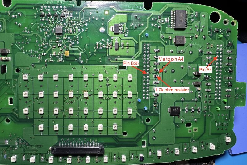
* The +12v source for pin B25 is cluster pin A4, through a series 1.2k ohm resistor: Pin A4 is the "Key Contact" pin, which has +12v applied to it whenever the key is in the RUN position
* During normal startup, the airbag CU (Control Unit) shorts cluster pin B25 to ground, by means of the A7<>B25 lead (the one mentioned in factory service manual test #3), which causes the airbag light to illuminate
* When pin B25 is in a full-short-to-ground condition, the 1.2k ohm series resistor (mentioned above) limits current (from grounded pin B25 to pin A4 and +12v) to ~10mA, so no fuses are blown
* The drop in voltage on pin B25 (when it is pulled to ground by being shorted) triggers cluster LED control circuitry to illuminate the airbag light
* Once the airbag control unit has finished its function test, it breaks the pin B25 short to ground, extinguishing the airbag light
* The above operation model matches the sequence of airbag light behavior that I know from years of personal experience driving this Boxster
So there are (at least) two basic circuit-level reasons that the airbag light might be illuminated:
1. Cluster pin B25 is shorted, or partially shorted, to ground
2. Cluster pin B25 is not receiving its normal ~12v supply voltage from cluster pin A4
If memory serves, the issue with the donor cluster board appeared to be caused by a shorted, faulty component. I found it by removing (desoldering) various components and testing them; but I forgot to document the exact culprit, as I was more focused on understanding the circuit at that time.
Armed with the above knowledge, I removed my vehicle's original cluster and put it on the bench in the same test configuration
Fixing my car's original instrument cluster board
By means of visual inspection under a stereo microscope at 3.5x-7x magnification, I determined that the problem was caused by a common electronics issue:
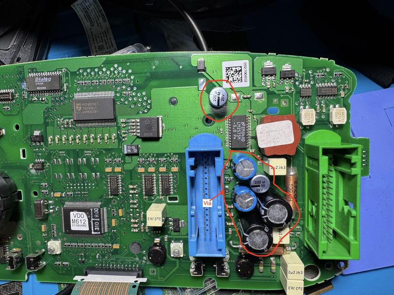
* Power-filtering electrolytic capacitors sit directly between the blue and green cluster wiring harness connectors
* These electrolytic caps are known commonly to leak, particularly after years of service, and esp. in high-temp environments; and their electrolyte fluid is typically caustic. They cause many electronic device failures
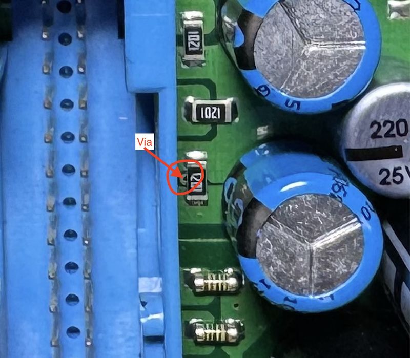
* One or more of these electrolytic caps leaked, and the fluid corroded a circuit board via connected from the 1.2k ohm resistor (on pin B25) to cluster pin A4
* Note: A circuit board via is an inter-layer (intra-board) board trace, which connects different layers, sometimes in different areas of the board
* The 1.2k ohm resistor (mentioned previously) is (electrically) between the via and pin B25, so that whatever is connected to the via is connected THROUGH that resistor to pin B25 (as described earlier)
* On the donor board, this via connected directly (~0.5 ohms measured resistance) to cluster pin A4 (Key Contact)
* Note: This via connection to A4 may be physically indirect: I could not see the via traces, as they were between large pads on both top & bottom of the board; but the measured resistance/continuity of a non-corroded via indicates an effective short between it and pin A4
* On my vehicle's original cluster the via was completely corroded away by the leaked electrolyte fluid, and there was very high resistance from the 1.2k ohm resistor to pin A4
* I performed a routine 're-cap' on the board, replacing all electrolytic capacitors with new, high-hours-rated, automotive-rated parts from Mouser, and thoroughly cleaned the board of electrolyte residue
* Since cleaning did not fix the corroded via, I used small gauge magnet wire to connect the 1.2k ohm resistor directly to cluster pin A4, thereby restoring the necessary +12v supply to pin B25 through that resistor.
At this point, the original cluster board operated as designed (i.e. as it normally would in the vehicle) on the bench.
* I reinstalled the repaired cluster in the Boxster, cleared the fault code once more, and again restarted the car
* On startup, the airbag light now follows its normal sequence of illuminating briefly, then extinguishing; and the fault has not returned
* I unplugged the passenger seatbelt wiring harness connector to confirm that the airbag light would still illuminate for a system fault. It did; and reconnecting the harness + clearing the fault again extinguished the light (i.e. returning the system back to normal, no-faults behavior).
Once you have eliminated wiring and other airbag system issues (e.g. seatbelt receiver wiring, fuses, etc.), it's much easier to diagnose the cluster itself given some kind of idea about how it works. With a full cluster circuit board schematic, the above process would have taken a few hours. Starting blind, it took me several weeks (in the evenings after work) of testing, ordering & waiting for parts, exploring, trying various solutions, consulting the Bentley manual & dozens of forum threads + images, testing again, fixing, etc.
Hopefully the above information will raise our overall level of communal knowledge about this system, enabling owners to better diagnose and troubleshoot similar issues.
I have provided Mouser part numbers (below) for the three different types of electrolytic capacitors required to 're-cap' a 2001-era cluster. If you open up the cluster to fix any issues, it's wise to re-cap: These caps inevitably go bad; and catching them BEFORE they leak is even better than fixing the damage caused by a leak.
Mouser.com part numbers/links for electrolytic capacitors:
Below are images of the donor board, highlighting the electrolytic caps (circled in red), via (top and bottom of board views), the 1.2k ohm surface mount resistor, relevant pins, etc. (I have higher-resolution copies; but the forum limits to 2MB files. Apologies if things don't show with sufficient detail)
NOTE: I think someone had already worked on this donor board. There was evidence of uncleaned solder flux, along with 2 of the electrolytic capacitors that appeared possibly to have been replaced. The 'replacement' parts were of a better quality/type than what I found in my original board; so I ordered my new parts based on those.
All best
--
Mike


 Boxster

 2000 Porsche Boxster S
 Linear Mode


