Go Back   986 Forum - The Community for Porsche Boxster & Cayman Owners > Porsche Boxster & Cayman Forums > DIY Project Guides

Post Reply
 
LinkBack Thread Tools Display Modes
Old 02-16-2015, 05:17 AM   #1
Registered User
 
Join Date: Jun 2014
Location: LB, Germany
Posts: 1,526
Hello flaps10,

in germany we do have specialized companies that can do Lokasil and Nikasil coatings on used/worn cylinders. Maybe you should do a research if some companies in the US offer that too.

Steel sleeves in aluminium blocks have some big disadvantages, because of different expansion of the the different metals at higher temperatures.

Regards
Markus
Smallblock454 is offline   Reply With Quote
Old 02-18-2015, 01:50 PM   #2
Registered User
 
flaps10's Avatar
 
Join Date: Jul 2014
Location: Tacoma
Posts: 429
Well I'm finally on my way back together. I had been waiting for my order from LN Engineering which included the tapered sleeve ring compressor. They had been on back order for a few weeks. When it arrived I was out of excuses.

Well, almost out. Knowing that one of the modes of failure for the M96 is when one of the sprockets on the IMS slips, causing an instant timing deviation and possible catastrophic failure (if you consider valves impacting pistons to be catastrophic anyway), I wanted to do something to mitigate the potential.

I had stumbled across this video while surfing the issue:
https://www.youtube.com/watch?v=XP6GwqLvD7Q

So I did it at home. I don't have a milling machine with DRO, but I do have a drill press and a half way decent set up for drilling holes in metal stuff:


Okay now I'm out of excuses.

I decided to install the IMS bearing into the shaft before putting the shaft in. No reason not to, and it sure is easier to reach.

I'm going to be a guinea pig for the EPS roller bearing. The bearing went in the freezer for what turned out to be a couple of days and my intermediate shaft went in the oven for a while to gain as much elbow room as possible. (Warning: did cause a funny smell I had to explain to my woman). Coming out of the oven the shaft went vertical into my vise so the entire load of me 'encouraging' the bearing into place didn't transmit through anything but the gear I pressed it in to. I used their install tool and a plastic dead blow hammer to get the bearing to sit solid in the pocket.
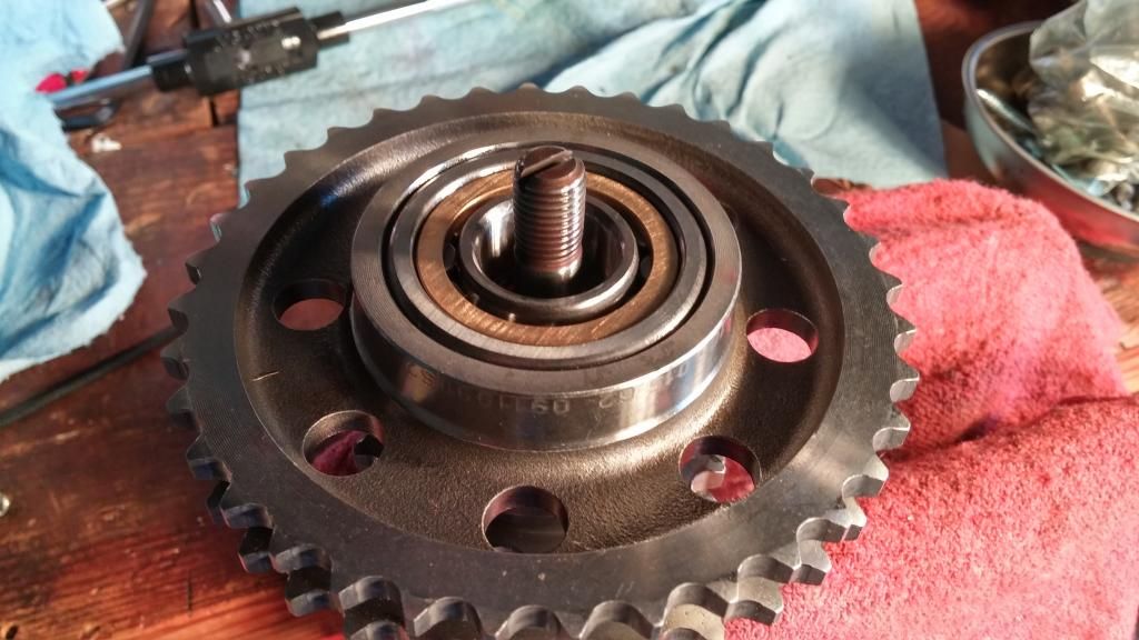

In.

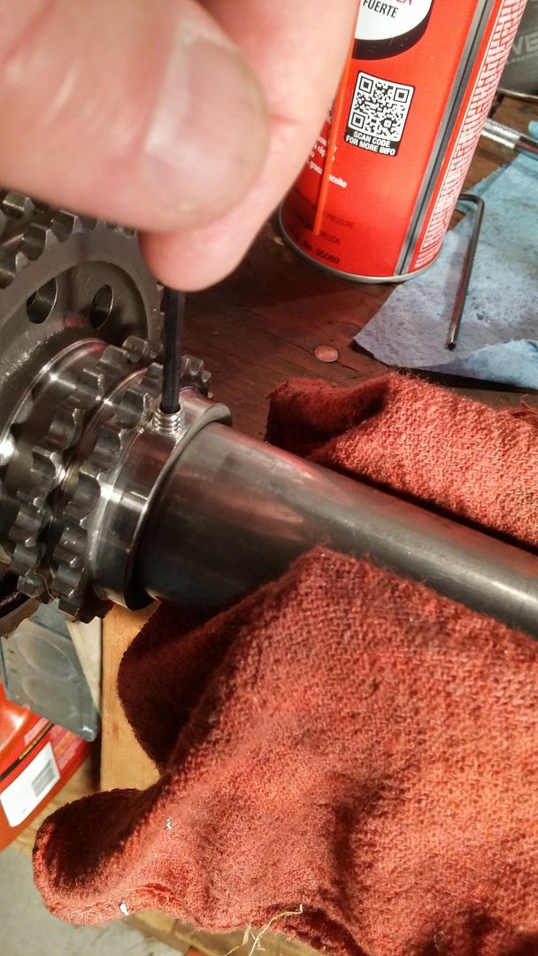
Other things about the EPS bearing. The current price on the vertex site is $439, and it turns out that includes the kit to do the oil feed. The kit consists of a tapered punch and the revised oil pump drive shaft. Having seen the images of the groove in the oil pump drive I was surprised to find out the groove is quite small (0.093" wide and 0.005" deep by my measure). The punch? Not a fan. The instructions tell you to punch a 1-3mm hole in the back of the drive shaft hole. That's a huge range. Being as my shaft was still on my bench, drilling a 0.078" hole and blowing the shaft out with compressed air seemed like a better option.


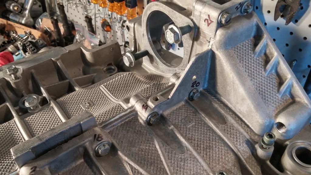
I fit the bearing carrier to the crankcase half for cylinders 1-3. There are two bolts which exist to hold the bearing carrier to this case half but they are both at the same end of the engine (the rear in our boxster case). Porsche special tool #blah, blah lets you use a cylinder head bolt to secure the other end.


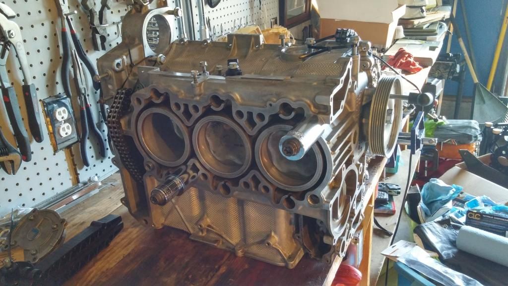
As you can see I have two such special tools which do double duty as 1/2" drive sockets. Those head bolts are just tight enough to keep the bearing carrier from having any slop and are not in any danger of marking up the mating surface common to the cylinder head.


The two bolts dedicated to holding the carrier to the case will eventually be joined by a really long one from the opposite case half. The manual I have tells me not to bring those bolts to final torque until the case halves are bolted together. So just like the head bolts being used to hold the carrier to the case, I have them just snug enough to do the job.

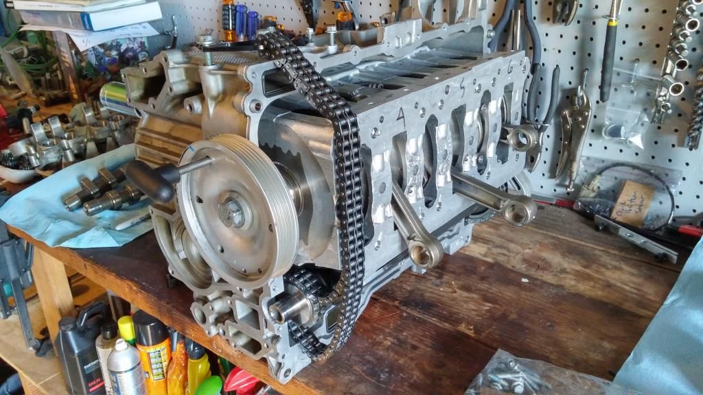
You can also see pistons 1-3 in place in these pictures. Thanks to the tapered sleeve ring compresser, getting them in was stupid easy and actually a little fun.

The crank pulley is on in order to facilitate rotating the crank shaft to the various positions required to install the pistons.

The basic process it rotate the engine so the rod journal is the furthest away from the cylinder head surface. You take a piston with connecting rod attached, remove the bearing cap and feed it into your ring compressor (lots of clean oil on everything). Then you feed the assembly into the engine from the cylinder head side. It found it quite easy to reach into the bearing carrier and gently guide the rough scratchy end of the connecting rod to meet the crankshaft.

You've already triple checked the piston orientation (cylinder number, "up", etc) and now it's time to get super careful with the connecting rod caps. First off, orientation which I made simple by running a random line with a fat sharpie across the joint of the rod and cap before taking it apart. The pen mark also makes it very easy to see side to side mismatch.

The super careful part is as follows. These (stock) rods are of the "fractured" variety. They literally forge the connecting rod and do all the machining, and the break it in a predetermined spot. The fractured spot has a granulated structure to it, and the idea is that it takes place of any dowel pins, etc. and maintains precise location.

You can't just sock your rod bolts down and assume that the alignment is dead perfect both top and bottom. You need lots of light and get your face in there and make sure. I gently installed the rod bolts while holding the cap in place, just finger tight. Then I pulled out the pin holding the crank pulley and rotated the engine back and forth to check to make sure the rod caps were going on absolutely perfectly and snugged the bolts back and forth. I had to back up a few times over all but it wasn't really difficult.

Once happy I finished torquing them down.

Next I spent an hour going over the case half for cylinders 4-6, getting rid of any remaining sealant and then blowing the hole thing out with my air compressor.

When I get home today my latest pelican order will be on the porch which contains Drei Bond and head gaskets.
flaps10 is offline   Reply With Quote
Old 02-18-2015, 04:12 PM   #3
Registered User
 
jaykay's Avatar
 
Join Date: Sep 2009
Location: toronto
Posts: 2,668
Very interesting....what material are you using to ensure that the screw never backs out? Is there an issue with balancing such that another screw is required at 180 degrees ...and some grinding after balancing this component?

I am very curious about this roller bearing; I have never heard anything about it. Is all thrust on the IMS resolved at the other end such that rollers will survive? No wishes to start a bearing feud ....just straight technical questions.

Cheers
__________________
986 00S

Last edited by jaykay; 02-18-2015 at 04:21 PM.
jaykay is offline   Reply With Quote
Old 02-18-2015, 04:42 PM   #4
Registered User
 
Join Date: May 2014
Location: S.California
Posts: 2,029
Flaps
Well done, & thanks for sharing.
I am just a few steps ahead of you in the process.I make far too many mistakes to share with everyone.It would be humiliating ;-).

A few hints for others.
1."Jugs" - Wiseco and others sell these(Jegs/Summit etc) 93mm. Use lots of oil.

2. I splurged on ARP bolts for the bearing carrier,rods and head. The OEM bolts were about the same price and imho inadequate. I am very impressed with ARP's material science/engineering. Their Marketing is questionable. I had to buy items intended for a 996 -they weren't sure if it would fit a 3.2l Boxster ! Now they know -from me!
The expert I found is:
Alex Crostic - Specialty Products Coordinator
Automotive Racing Products, Inc. (ARP)
Web: ARP | The Official Web Site
When you compare Porsche fasteners with ARP it is like a comparison between hardware store general purpose made-in-china. Sad but true.

3. John Edwards - Costa Mesa R&D Brilliant guy . I use him. He is a wonderful curmudgeon. Doesn't suffer fools. So don't expect Engineering/Machining 101 from him over the phone.He literally wrote the book on engine machining for Sunnen. You will be talking to a god.
Sunnen's Complete Cylinder Head and Engine Rebuilding Handbook: John G. Edwards: Amazon.com: Books
He has lots of relevant videos on Porsche, Subaru, Fiat. If you want to impress him - talk to him about Zastava gearboxes for the 128. Pure porn for him! And sadly for me too .

hope this helps/amuses.Happy Boxster repairing.

Last edited by Gelbster; 11-05-2015 at 07:20 PM.
Gelbster is offline   Reply With Quote
Old 02-18-2015, 05:09 PM   #5
Registered User
 
Join Date: May 2014
Location: S.California
Posts: 2,029
"I'm going to be a guinea pig for the EPS roller bearing." + DOF
Woops you do not have the 'real' DOF - if by that you mean a direct feed from the cam cover port. Big difference compared to the oil-pump drive-shaft hack ,er modification.
Flaps you are performing a great service to the M96 community.Thank you. I applaud your potential sacrifice of an expensively repaired M96 - just to prove the futility (I sincerely hope I am wrong!) of defying the IMSB gods and gurus.

We have had a few inconclusive debates about roller vs. ball bearing. I prefer field experiments - particularly with someone elses engine-yours !

My pure and unsubstantiated WAG is that the oil feed to the bearing will 'save' the roller bearing .That is a gratuitous & uninteresting assertion. The significant part is WHY? In theory( unsubstantiated theory!) ,the new oil supply will cool the bearing sufficiently and you will use oil with enough thermal shear resistance(& change frequently) to offset the clumsy inherent characteristics of the roller bearing. You will drive it gently enough to never snap the oil pump drive and you will never 'tax' the engine.
After a few thousand miles, you will declare a triumph for the roller bearing IMSB and have many devoted followers. You may even get an email congratulation from Feelyx(they guy who championed the roller bearing idea long ago and on a different Forum).
Now if you used a real DOF from the cam cover - that would be fascinating ! But then you wouldn't need the roller - a deep grove ball bearing would be adequate?Oh no , another IMSB thread!
You may find some interst/amusement here:
http://rennlist.com/forums/boxster-and-boxster-s-986-forum/851476-broke-piston-with-baum-circlip-tool-help-please.html

Sincere thanks for your story and good luck !

Last edited by Gelbster; 02-19-2015 at 08:43 AM.
Gelbster is offline   Reply With Quote
Old 02-18-2015, 08:23 PM   #6
Registered User
 
flaps10's Avatar
 
Join Date: Jul 2014
Location: Tacoma
Posts: 429
Jaykay,
If you watch the video in the link i posted you'll see how the set screw is retained. The video was produced by the person gelbster mentions - John Edwards of Costa Mesa R&D. Basically by careful use of the tapered tap, you can cause the screw to basically run aground against the uncut portion of the threads at the bottom of the hole at the exact same time the screw goes below flush on the outside.

He uses some high temp thread locking goo. I used JB Weld. That screw is not going anywhere. I considered running another screw at 180 degrees to balance the first, but the weight of a set screw is going to be very close to the weight of the materiel removed during drill and tap. Given the difference between those two weights relative to the mass of the shaft , I'm not going to lose any sleep over balancing.

Gelbster,
I won't ever declare victory, and certainly not after a few thousand miles. The only time my vehicles are driven carefully is while waiting for temps to come up. What i will do is share what i learn along the way. This has been a very educational process.

I too am running the ARP rod bolts. I got the bearing carrier bolts but they came with the instruction to align bore the carrier. That's not happening this time around, so I'm sitting on those bolts until next time.
flaps10 is offline   Reply With Quote
Old 02-23-2015, 04:31 PM   #7
Registered User
 
flaps10's Avatar
 
Join Date: Jul 2014
Location: Tacoma
Posts: 429
As I type I'm reminded of the old Monty Python segue: "And now for something completely different".

This next series of steps with the M96 is really the only part which has caused me to stress out, because I've never done anything like it. I've seen the apt reference that installing pistons 4-6 is akin to building a ship in a bottle.

I needed a lot of practice. And practice I did.

Getting the wrist pin retaining clips in is challenging enough just sitting on your wood bench with good light. If it doesn't seat perfectly there is a very high probability that it will jump out during the first engine run and sod things up for good.

So I got a bunch of practice with my tools. After marking the tool for depth at each cylinder location I started installing piston #6 (the furthest one) and went through the process.

In my first 10 attempts at inserting the the retaining clip for cylinder #6 I got it properly seated 1 time. That was not anything like a good enough average to bother with breaking out the Drei Bond. So I kept at it, fine tuning my technique, polishing the segment of the tool which has to mate up perfectly with the piston before "firing" the wrist pin. Finally I began getting it consistently and now I can tell just by the feeling through my hands that it is seating property.

Next, I rotated the case half so I couldn't see inside because that is cheating and I wouldn't be able to do that with the case halves together. Here is where my earlier practice paid off because I was getting pretty good at setting up the wrist pin clips in the tool just using my fingers.

Cylinders 5 and 4 were much easier. If anything the tool runs a little sloppier the more it comes out of the case and it would be easy to mess up if you get complacent.

Next I cleaned both case halve joining surface with acetone, then got out the Drei Bond and made a bead, then had my youngest son help me by guiding the timing chain and connecting rods while I lowered the case half onto the other one.

I hurriedly got screws in all the locations and then used my air ratchet wrench to bring the case halves just snug. Then I whipped out the torque wrench and got all the case half screws to spec, in the order the book says. I'm not ashamed to admit that I use a sharpie pen to write the torque sequence directly on the engine. When I'm done an acetone rag destroys any evidence that I suffer from CRS.


Now I have to position the engine so that the cylinder bores are upright and I can rotate the crankshaft. Then we'll see if I really practiced enough.
flaps10 is offline   Reply With Quote
Post Reply


Posting Rules
You may not post new threads
You may not post replies
You may not post attachments
You may not edit your posts

BB code is On
Smilies are On
[IMG] code is On
HTML code is On
Trackbacks are On
Pingbacks are On
Refbacks are On


All times are GMT -8. The time now is 08:05 PM.


Powered by vBulletin® Version 3.8.7
Copyright ©2000 - 2025, vBulletin Solutions, Inc.
Content Relevant URLs by vBSEO 3.6.0
Copyright 2025 Pelican Parts, LLC - Posts may be archived for display on the Pelican Parts Website -    DMCA Registered Agent Contact Page