 02-21-2019, 10:07 PM
|
#1
|
|
Registered User
Join Date: Feb 2019
Location: LA, CA
Posts: 1
|
I just did this to my recently acquired 986 and now my Dad wants it in his car. Thanks to everyone who made this a successful DIY project. There is so much good info on this thread.
Does anyone know if this will work on a 997?
|

|

|
|
06-01-2014, 05:40 PM
|
#2
|
|
On the slippery slope
Join Date: Mar 2014
Location: Austin and Palm Springs
Posts: 3,807
|
Quote:
Originally Posted by JayG

Just ordered all the parts today. Should have everything by the end of next week and I'll build/install over next weekend
Arduino Nano clone from ebay $9
Rest of parts from DigKey $13
This will be my first Adruino project of what I expect to be several more.
Thanks Polaris, you instructions are great and thanks for the code.
Ill post how it goes after the install
|
Ok, I got it all wired and connected to the switch and harness
unfortunately it does not work. I get a clicking sound from both the relay and somewhere in the top. If I hold the switch, it clicks and the top moves in a very slow stepping manner
I did a minor change to the design, I used pins D7&8 instead of 8&9. I did change the definitions to reflect that.
I am not a programmer and this is the first time I have used an Arduino
any ideas?
__________________
2004 Boxster S 6 speed - DRL relay hack, Polaris AutoTop DIY
2004 996 Targa Tip
Instructor - San Diego region
2014 Porsche Performance Driving School
2020 BMW X3, 2013 Ram 1500, 2016 Cmax, 2004 F-150 "Big Red"
|

|
|
|
06-01-2014, 05:49 PM
|
#3
|
|
Registered User
Join Date: Sep 2013
Location: Bay Area, CA
Posts: 310
|
AutoTop DIY
Quote:
Originally Posted by JayG
Ok, I got it all wired and connected to the switch and harness
unfortunately it does not work. I get a clicking sound from both the relay and somewhere in the top. If I hold the switch, it clicks and the top moves in a very slow stepping manner
I did a minor change to the design, I used pins D7&8 instead of 8&9. I did change the definitions to reflect that.
I am not a programmer and this is the first time I have used an Arduino
any ideas?
|
As a first attempt, check your wiring, specifically the 10k pulldown resistors on pin 7,8 be sure they're there and the connection is secure.
If you soldered the everything, sometimes a solder joint can look good but internally it's actually not making a good connection. By moving the wires during operation, you will see a change in operation if you have a bad connection.
__________________
If you are interested in a Comfort-Top module, please visit:
https://www.enhancedautomods.com/shop/comfort-top
Last edited by Shehadehd; 06-01-2014 at 05:54 PM.
|
|
|
|
|
06-01-2014, 06:17 PM
|
#4
|
|
On the slippery slope
Join Date: Mar 2014
Location: Austin and Palm Springs
Posts: 3,807
|
Quote:
Originally Posted by Shehadehd
As a first attempt, check your wiring, specifically the 10k pulldown resistors on pin 7,8 be sure they're there and the connection is secure.
If you soldered the everything, sometimes a solder joint can look good but internally it's actually not making a good connection. By moving the wires during operation, you will see a change in operation if you have a bad connection.
|
thanks for the fast reply
I should preface that that I have done a lot of soldering, I used to build and repair pro audio gear and soldered about a million XLR and multipin connectors.
In any case, I checked the pull down resistors, good connections
I tried the wiggle on all connections with no luck
In order to get any movement, I have to hold the button and instead of smooth operation, it is clicks and steps as it moves
Could it be a bad board?
__________________
2004 Boxster S 6 speed - DRL relay hack, Polaris AutoTop DIY
2004 996 Targa Tip
Instructor - San Diego region
2014 Porsche Performance Driving School
2020 BMW X3, 2013 Ram 1500, 2016 Cmax, 2004 F-150 "Big Red"
|
|
|
|
|
06-01-2014, 06:26 PM
|
#5
|
|
Registered User
Join Date: Sep 2013
Location: Bay Area, CA
Posts: 310
|
Quote:
Originally Posted by JayG
thanks for the fast reply
I should preface that that I have done a lot of soldering, I used to build and repair pro audio gear and soldered about a million XLR and multipin connectors.
In any case, I checked the pull down resistors, good connections
I tried the wiggle on all connections with no luck
In order to get any movement, I have to hold the button and instead of smooth operation, it is clicks and steps as it moves
Could it be a bad board?
|
More likely bad pins than a bad board. You can always try four different pins and see what happens. If both opening and closing the top acts the same, then maybe the transistors aren't working properly. Make sure you didn't wire them backwards... you might also want to check to see if the 1k resistor to the transistor is an acceptable value for the transistors you're using.
|
|
|
|
|
06-02-2014, 10:28 AM
|
#6
|
|
On the slippery slope
Join Date: Mar 2014
Location: Austin and Palm Springs
Posts: 3,807
|
Did some more testing this morning
When I meter the output pins (D2 & D3) I do get ~2.5v when I close the switch. The problem is it does not stay latched, in other words it is high only while I close the switch. It doesnort matter how long I keep teh switch closed, as short as momentary or longer. the same result.
Now that is on a meter and one of the problem was that the top relay chattered and the top "stepped" as it was moving.
I am wondering if my board is bad, or the other case is an error in the code
__________________
2004 Boxster S 6 speed - DRL relay hack, Polaris AutoTop DIY
2004 996 Targa Tip
Instructor - San Diego region
2014 Porsche Performance Driving School
2020 BMW X3, 2013 Ram 1500, 2016 Cmax, 2004 F-150 "Big Red"
|
|
|
|
|
06-05-2014, 07:23 AM
|
#7
|
|
Registered User
Join Date: Apr 2013
Location: Springfield, Oregon
Posts: 62
|
JayG,
I have a couple nanos on the way. I should hopefully have them by tomorrow (crossing my fingers for today). I'll build one up over the weekend and see how it goes and if I run into anything similar to you.
|
|
|
|
|
06-08-2014, 12:49 PM
|
#8
|
|
Registered User
Join Date: Apr 2013
Location: Springfield, Oregon
Posts: 62
|
Got the Arduino Nanos on Friday. I ordered the nanos that don't have the on-board USB to serial to save space and complexity. The only problem is I can't for the life of me find my "ftdi friend" usb to TTL converter to program them. I just ordered a replacement, I'll update when it gets here and I can program the nano. It'll undoubtedly be at least a week for it to get here.
|
|
|
|
|
06-08-2014, 12:56 PM
|
#9
|
|
Registered User
Join Date: May 2013
Location: North Alabama
Posts: 2,079
|
Could you give us a pinout (EBC) on the transistors...the voltage regulator is pretty self explanatory.
|
|
|
|
|
06-08-2014, 02:47 PM
|
#10
|
|
On the slippery slope
Join Date: Mar 2014
Location: Austin and Palm Springs
Posts: 3,807
|
the transistor is acting like a switch and switching ground. It doesn't matter which way they are connected as long as the base is connected via the resistor to pin 2 or 3 as applicable. The middle pin is the base.
Polaris,
Can you email the actual Arduino sketch file? I would like to try what you got working before.
__________________
2004 Boxster S 6 speed - DRL relay hack, Polaris AutoTop DIY
2004 996 Targa Tip
Instructor - San Diego region
2014 Porsche Performance Driving School
2020 BMW X3, 2013 Ram 1500, 2016 Cmax, 2004 F-150 "Big Red"
|
|
|
|
|
06-11-2014, 12:10 PM
|
#11
|
|
Registered User
Join Date: Apr 2012
Location: Riverside, CA
Posts: 1,666
|
JayG I took a look at the code and it seems fine and compiles, however I am using the Arduino v1.1 software on a Win7 PC.
With this and other projects I have worked on it seems that the newer versions of the Arduino software has more bugs.
Try Arduino version 1.1.x
Also, the transistor orientation is important since a transistor can act as a diode and only allow current to flow in 1 direction.
If the transistors are backwards you may only be able to raise , lower or do neither.
Does anyone see any benefit to making the Arduino boards any smaller?
If so I may try to implement this on a TI EZ430-F2012 which is smaller literally than your thumbnail.
__________________
"It broke because it wants to be Upgraded  "
2012 Porsche Performance Driving School - SanDiego region
2001 Boxster S, Top Speed muffler, (Fred's) Mini Morimotto Projectors, Tarret UDP,
Short Shifter, Touch Screen Dual Din Radio, 03 4 Bow glass Top (DD & Auto-X since May 17,2012)
Last edited by jb92563; 06-11-2014 at 12:17 PM.
|
|
|
|
|
06-11-2014, 01:17 PM
|
#12
|
|
On the slippery slope
Join Date: Mar 2014
Location: Austin and Palm Springs
Posts: 3,807
|
Quote:
Originally Posted by jb92563
JayG I took a look at the code and it seems fine and compiles, however I am using the Arduino v1.1 software on a Win7 PC.
With this and other projects I have worked on it seems that the newer versions of the Arduino software has more bugs.
Try Arduino version 1.1.x
Also, the transistor orientation is important since a transistor can act as a diode and only allow current to flow in 1 direction.
If the transistors are backwards you may only be able to raise , lower or do neither.
Does anyone see any benefit to making the Arduino boards any smaller?
If so I may try to implement this on a TI EZ430-F2012 which is smaller literally than your thumbnail.
|
I can compile and load perfectly, its just it does not seem to work properly
Good catch on the transistor. Like I said, it been a very long time since I played around with electronic components
I don't see where I can download 1.1, but I have tried 1.5.6 and 1.0.5
Hopefully Polaris will be able to shed some light on this when he is able to try a NANO
__________________
2004 Boxster S 6 speed - DRL relay hack, Polaris AutoTop DIY
2004 996 Targa Tip
Instructor - San Diego region
2014 Porsche Performance Driving School
2020 BMW X3, 2013 Ram 1500, 2016 Cmax, 2004 F-150 "Big Red"
Last edited by JayG; 06-11-2014 at 06:46 PM.
|
|
|
|
|
06-11-2014, 07:56 PM
|
#13
|
|
Registered User
Join Date: Apr 2012
Location: Riverside, CA
Posts: 1,666
|
__________________
"It broke because it wants to be Upgraded "
2012 Porsche Performance Driving School - SanDiego region
2001 Boxster S, Top Speed muffler, (Fred's) Mini Morimotto Projectors, Tarret UDP,
Short Shifter, Touch Screen Dual Din Radio, 03 4 Bow glass Top (DD & Auto-X since May 17,2012)
|
|
|
|
|
06-11-2014, 08:22 PM
|
#14
|
|
On the slippery slope
Join Date: Mar 2014
Location: Austin and Palm Springs
Posts: 3,807
|
Quote:
Originally Posted by jb92563
|
That's what I have been using. I tried 1.5.6 today as well
The problem I have is not compiling or loading the code, its that it doesn't work properly
The top motor only runs as long as I have the switch pushed, just like stock. A momentary push does not keep the top moving
__________________
2004 Boxster S 6 speed - DRL relay hack, Polaris AutoTop DIY
2004 996 Targa Tip
Instructor - San Diego region
2014 Porsche Performance Driving School
2020 BMW X3, 2013 Ram 1500, 2016 Cmax, 2004 F-150 "Big Red"
|
|
|
|
|
06-20-2014, 09:18 AM
|
#15
|
|
Registered User
Join Date: Apr 2013
Location: Springfield, Oregon
Posts: 62
|
JayG, any update on getting a picture of your setup?
I'm still waiting on the usb to serial programmer to get here.
|
|
|
|
|
06-20-2014, 09:34 PM
|
#16
|
|
On the slippery slope
Join Date: Mar 2014
Location: Austin and Palm Springs
Posts: 3,807
|
Quote:
Originally Posted by Polaris
JayG, any update on getting a picture of your setup?
I'm still waiting on the usb to serial programmer to get here.
|
I'm traveling currently and will be back on Monday. I'll take some pics then
__________________
2004 Boxster S 6 speed - DRL relay hack, Polaris AutoTop DIY
2004 996 Targa Tip
Instructor - San Diego region
2014 Porsche Performance Driving School
2020 BMW X3, 2013 Ram 1500, 2016 Cmax, 2004 F-150 "Big Red"
|
|
|
|
|
06-21-2014, 07:32 PM
|
#17
|
|
Registered User
Join Date: Jun 2013
Location: Melville NY
Posts: 80
|
Polaris please send me a note if you can make me an auto-top . I would like to buy one from you. Thanks, Lee NY
|
|
|
|
|
06-26-2014, 09:11 AM
|
#18
|
|
On the slippery slope
Join Date: Mar 2014
Location: Austin and Palm Springs
Posts: 3,807
|
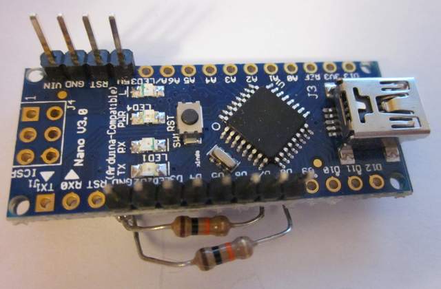
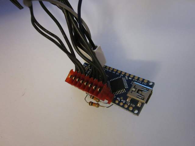
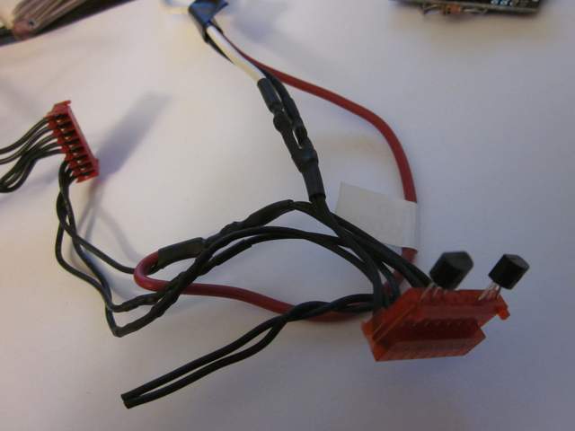
OK, finally got a chance to take a few pics
Polaris,
A few questions
Have you been able to get a NANO to work ?
Do you have any special libraries loaded?
the reason I ask, is that you define some variables and I dont see them referenced anywhere in your posted code
#define openTime 15600;
#define closeTime 16400;
I have double and triple checked my wiring. I did make 1 modification, the pins used for the outputs so I could use the header cable I had. I changed the pins in the code as well
The header cables also make a great transistor socket

__________________
2004 Boxster S 6 speed - DRL relay hack, Polaris AutoTop DIY
2004 996 Targa Tip
Instructor - San Diego region
2014 Porsche Performance Driving School
2020 BMW X3, 2013 Ram 1500, 2016 Cmax, 2004 F-150 "Big Red"
|
|
|
|
|
07-16-2016, 06:13 PM
|
#19
|
|
Registered User
Join Date: Aug 2014
Location: Fort Collins, Colorado
Posts: 345
|
Quote:
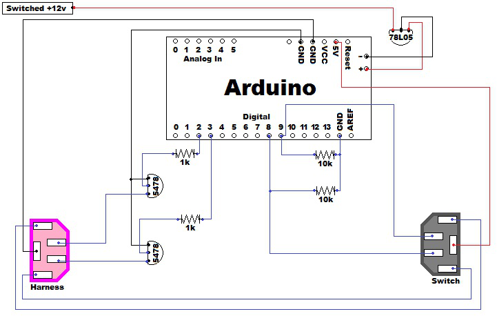
Originally Posted by Polaris
Schematic:
 |
Quote:
Originally Posted by JayG
OK, finally got a chance to take a few pics
|
OK. I am starting the project and have a few questions. I was a code guy back in the day but have done some electronics. I am using a breadboard to wire it up before I solder everything together.
Here is a picture of my nano. I am trying to figure out how to match the pinouts from Polaris's Arduino. Mine is more like JayG.
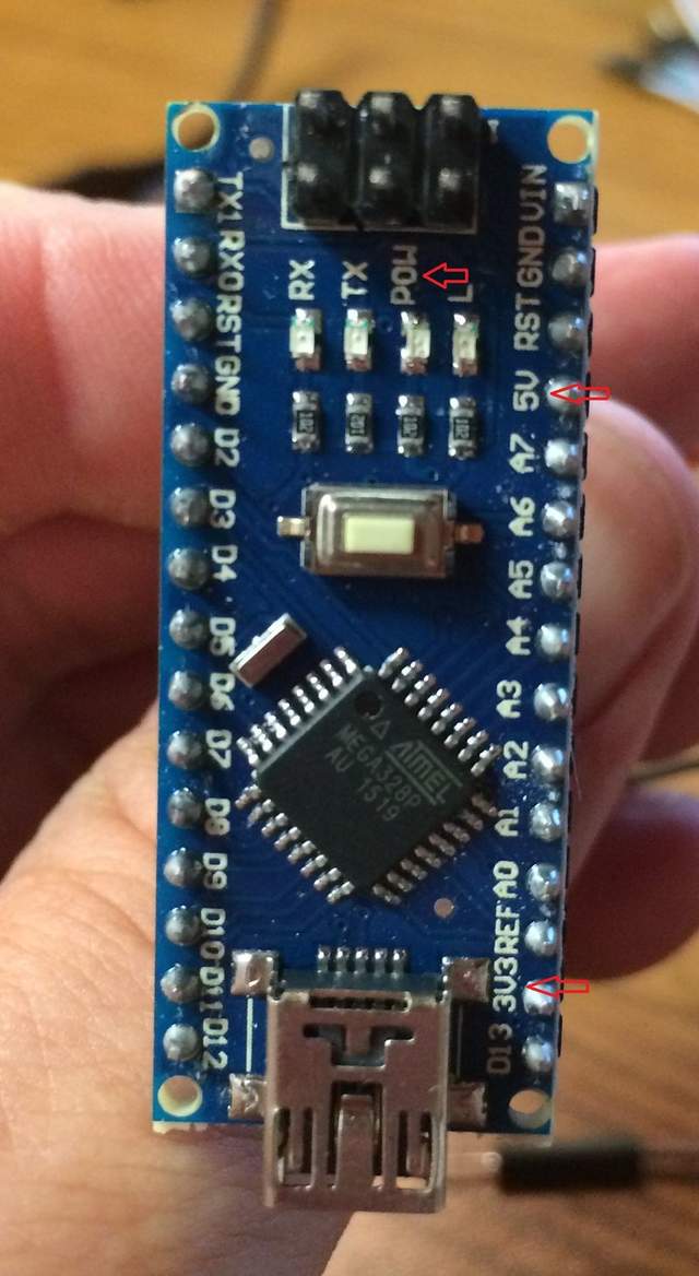
I assume that the "-" on the end is simply ground and will solder to the other ground wires. The "+" is a question as I have both 5v, 3.3v and pow pins. So, which do I connect the power regulator to?
__________________
2001 Boxster S - Midnight Blue Metalic
|
|
|
|
|
06-26-2014, 03:52 PM
|
#20
|
|
Registered User
Join Date: Apr 2013
Location: Springfield, Oregon
Posts: 62
|
The MovementCount veritable should definitely be getting set to either openTime or closeTime depending on the button pressing. Maybe I posted the wrong version of the code....like a bone head. I'll have a look through my files when I get home from work.
|
|
|
|
| Thread Tools |
|
|
| Display Modes |
 Hybrid Mode Hybrid Mode
|
 Posting Rules
|
You may not post new threads
You may not post replies
You may not post attachments
You may not edit your posts
HTML code is On
|
|
|
All times are GMT -8. The time now is 05:12 AM.
| |


 2004 Porsche Boxster S
 2004 Porsche 996 Targa
 Boxy Grannis


