Go Back   986 Forum - The Community for Porsche Boxster & Cayman Owners > Porsche Boxster & Cayman Forums > Boxster General Discussions

Post Reply
 
LinkBack Thread Tools Display Modes
Old 10-11-2017, 06:22 PM   #21
Registered User
 
redciv1's Avatar
 
Join Date: Jun 2014
Location: Dacula, Georgia
Posts: 264
Am I actually soldering on the gold contacts themselves?

redciv1 is offline   Reply With Quote
Old 10-11-2017, 06:29 PM   #22
1999 base
 
Meir's Avatar
 
Join Date: Dec 2011
Location: Coral Springs FL
Posts: 1,617
Garage
Quote:
Originally Posted by redciv1 View Post
Am I actually soldering on the gold contacts themselves?
Yes.
Unless you can confirm other points on the board that leads to the contacts.
Again. You will need a volt meter for that.
The gold holes on the top of the remote will be a good place to start.
Meir is offline   Reply With Quote
Old 10-11-2017, 06:32 PM   #23
Registered User
 
redciv1's Avatar
 
Join Date: Jun 2014
Location: Dacula, Georgia
Posts: 264
Would that be the 6 holes lined up in the middle of the board as I was looking at those initially.

Last edited by redciv1; 10-11-2017 at 06:35 PM.
redciv1 is offline   Reply With Quote
Old 10-11-2017, 06:37 PM   #24
Registered User
 
redciv1's Avatar
 
Join Date: Jun 2014
Location: Dacula, Georgia
Posts: 264
I have a multimeter, what would be the steps for testing on the board?
redciv1 is offline   Reply With Quote
Old 10-11-2017, 07:18 PM   #25
1999 base
 
Meir's Avatar
 
Join Date: Dec 2011
Location: Coral Springs FL
Posts: 1,617
Garage
You will have to set the voltmeter to diode test. That's the function when you touch the two probs together and the voltmeter beeps.
Then you need to place one of the probs on the connects, and run the other prob thru the holes, one at a time.
If the voltmeter beeps, that means that the hole and the conntact are connected.
In this case, you can solder the wire to the hole instead of the contact itself.
And yes. Start with the 6 holes in the center, and you can also check the 3 on the left.
My guess is that you will find the common. Not sure if you will find the other side.
Just by looking at the board.

Last edited by Meir; 10-11-2017 at 07:22 PM.
Meir is offline   Reply With Quote
Old 10-11-2017, 09:58 PM   #26
Custom User Title Here
 
particlewave's Avatar
 
Join Date: Mar 2012
Location: Ft. Leonard Wood
Posts: 6,163
Garage
Solder wires to the two terminals below the red dots I've placed in this photo.
Run one wire to terminal 4 on the switch and the other to either terminal 1 or 2.

That's it. No need to mess with anything else.
Attached Images
 
particlewave is offline   Reply With Quote
Old 10-12-2017, 11:16 AM   #27
Registered User
 
redciv1's Avatar
 
Join Date: Jun 2014
Location: Dacula, Georgia
Posts: 264
Hello Gentlemen, I appreciate all the help so far. I had a little emergency today with my cable modem out, so no anything. Will try to follow recommendations tonight or tomorrow and update soon.
redciv1 is offline   Reply With Quote
Old 10-12-2017, 06:07 PM   #28
Registered User
 
redciv1's Avatar
 
Join Date: Jun 2014
Location: Dacula, Georgia
Posts: 264
Ok, so this evening I had a chance to pull out he multi meter and check the board. Pics aren't great, but what I found is that the 4th hole, in the line of 6, when touched by one probe and then touching the top part of the contacts seems to be the common as the meter zero'd out each time on the top row of contacts and the middle row of contacts. So that means that ironically, #4 on the switch wire is soldered to the 4rh hole as the common and the other 2 wires each go to their respective contacts.
redciv1 is offline   Reply With Quote
Old 10-13-2017, 06:08 PM   #29
1999 base
 
Meir's Avatar
 
Join Date: Dec 2011
Location: Coral Springs FL
Posts: 1,617
Garage
Well done.
Meir is offline   Reply With Quote
Old 10-13-2017, 06:28 PM   #30
Registered User
 
redciv1's Avatar
 
Join Date: Jun 2014
Location: Dacula, Georgia
Posts: 264
Thank you sir. Will buy wire and hopefully solder everything this weekend. Thanks for the help.
redciv1 is offline   Reply With Quote
Old 10-20-2017, 05:52 AM   #31
Registered User
 
redciv1's Avatar
 
Join Date: Jun 2014
Location: Dacula, Georgia
Posts: 264
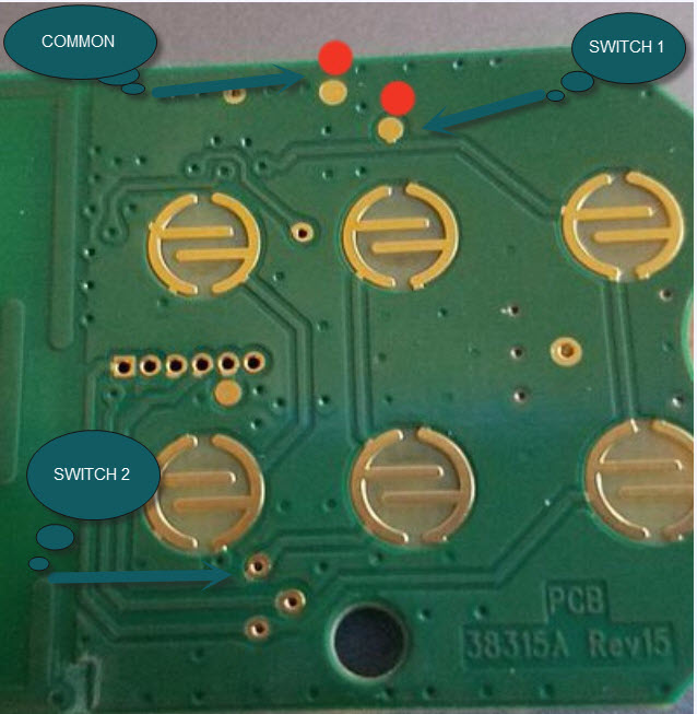
So I finally had a chance to work on the garage opener and window switch. I soldered as mentioned below with the COMMON going to 4th smaller hole on the board and then each SWITCH to the top part of the contacts. Nothing happened.
I then looked at the 2 contacts that Particlewave suggested and those Contcts worked with one of the doors, however it was the door my wife uses. So next task was to figure which hole on the board was for the other door...my door! After about 10 minutes and testing the remaining holes on the board, I was finally able to find the hole(contact) that controlled my door. I soldered it up and was able to get both doors working with the points noted. No pics of the soldered board as I immediately tape wires and placed back in the car.
Thanks for all the help Meir and Particlewave.
redciv1 is offline   Reply With Quote
Old 10-20-2017, 04:38 PM   #32
1999 base
 
Meir's Avatar
 
Join Date: Dec 2011
Location: Coral Springs FL
Posts: 1,617
Garage
See I told you it's simple
Meir is offline   Reply With Quote
Old 10-20-2017, 06:04 PM   #33
Registered User
 
redciv1's Avatar
 
Join Date: Jun 2014
Location: Dacula, Georgia
Posts: 264
Quote:
Originally Posted by Meir View Post
See I told you it's simple
Indeed!!! All set now.

redciv1 is offline   Reply With Quote
Post Reply


Posting Rules
You may not post new threads
You may not post replies
You may not post attachments
You may not edit your posts

BB code is On
Smilies are On
[IMG] code is On
HTML code is On
Trackbacks are On
Pingbacks are On
Refbacks are On


All times are GMT -8. The time now is 04:49 PM.


Powered by vBulletin® Version 3.8.7
Copyright ©2000 - 2024, vBulletin Solutions, Inc.
Content Relevant URLs by vBSEO 3.6.0
Copyright 2024 Pelican Parts, LLC - Posts may be archived for display on the Pelican Parts Website -    DMCA Registered Agent Contact Page