Bingo! We got it. All it needed was closing the top and bottom cabling trays (circled in red below). Thank god I took my time and didn't do the Electrical Routing before CFD, I would have had to run these wires all over again.
So there we have it. Every cubes of air is assigned to cooling the unit, no lost. Now if you ask me, this is the part where I get really exited in manufacturing this assembly. As long as I know this will work out as planed, I'm happy to trow the rest of the energy it needs for project completion. Goes fast from here

I'll run the thermal analysis this week, although not sure I'll upload as many visuals. Wouldn't want to bore anyone. Besides I am still waiting for a member to say "Hey, this is a CAR forum" lollll Pushing my luck with all this technical stuff

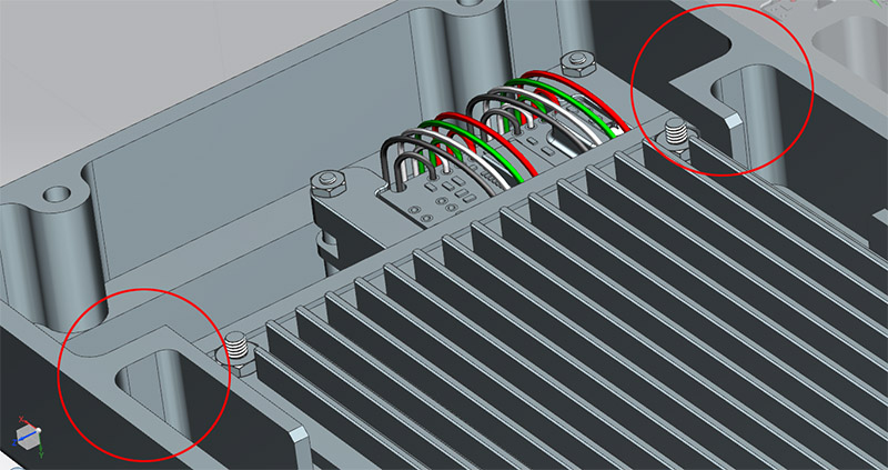
^ In red are are the two areas that needed closing, so to channel ALL of the air between those fins. Bye bye cabling trays however, can;t have it all!
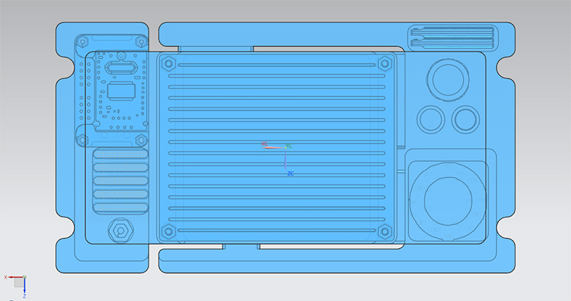
^ Our updated fluid domain. Notice the 3 openings to let the hot air evacuate the central PCB area. This is done with a slight negative pressure
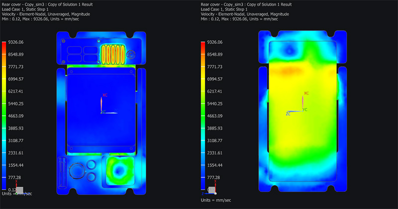
^ More than happy with this consistent flow. In fact, it performs far better than what I was hoping for (see for yourself in below grabs). Super exited about this. Hard work paying off, finally

^ Top view
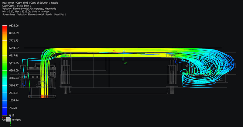
^ View from the side

^ And finally, with some of the layers turned ON... so you guys can visualize what's happening in there

Enjoy!