Hi guys!
I've wanted to do this for a while, and finally did it!
A manual control of the radiator fan, nothing new, but I didn't find any "good" DIY for it... I'll do my best.
I wanted it to be plug and play, without messing any original part, and without any soldering inside the car.
So here is what I used:
-These relay sockets (actually I just found those... half as much of what I paid!):
Amazon.com: Absolute USA 5-Pin 12 VDC Interlocking Relay Socket, 5 Set: Car Electronics
-Some 14AWG wire, you can find here:
Electrical Wire/Primary wire 85732R- ReadReviews onElectrical Wire #85732R
-Those male quick disconnect terminals:
Tyco Electronics 250 Series 16-14 AWG 10/Clam Male Disconnect Fully Insulated Nylon-CPGI-3-520107-2-10 - The Home Depot
They are the thickest I found.
-A 3 positions switch:
CARQUEST by BWD Multi Purpose Switch URS83: Advance Auto Parts
And you'll need a soldering iron (the 18w one at Home Depot is pretty good), heat shrink and solder.
Here is the final part:
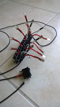
Hard to see anything with all these wires...
What
we want is a mean to ground the pin 85 of the 4 fan relays manually.
This is done with the three positions switch, one position for low, one position for high, and the middle position is off.
The
PCM still controls the fans, and even if you forget to turn the fans off, they will shut off when you turn the key off after 5sec.
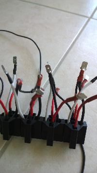
Two relays are for high speed and two are for low speed (and I just realized that on the picture I got the wires wrong!)
You can do the ghetto version by simply wrapping a wire around the pin directly on the relay... but I don't like it!
I measured
11.5A at high speed and 7.8A at low speed when the car is stationary. 14AWG should be alright for that.
The relay are positioned like this from right to left: [low speed right] [high speed right] [low speed left] [high speed left].
I replaced the wires going to the pins 87 and 30 with the 14AWG wire since the are the power wires, the other are only for control (low current).
I'll draw a clear schematic after... pictures are pretty useless here.
I hope it helps!
I haven't put the final assembly in the car yet.
Ben