After reading some of feelyx postings, I think I now know what he/she is talking about with the "leverage" on the bearing and how it causes deflection of the case walls.
At first I thought it was the case walls deflecting, causing leverage on the bearing, but now I realize it is leverage on the bearing leading to deflection of the case walls and the bearing flange.
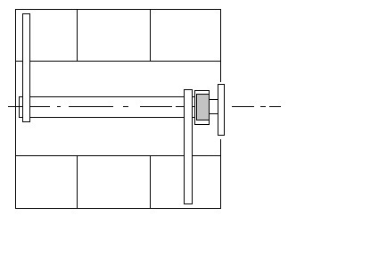
So as I see it, in a perfect world the IM shaft, bearing and flange are all in perfect alignment with the crank case as above.
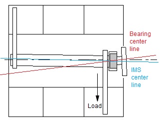
But when the IM shaft is driving the chains that are located near the bearing, the chains have leverage on the IM shaft, pulling it out of perfect alignment, putting the bearing in a bind.
I hope this is correct. It seems to make sense.
So my first question, is there a method to check the alignment of the bearing and flange when installed in the case. I imagine that if the bearing and flange are misaligned as in the second diagram, from the start, unloaded, early failure may be inevitable.
I was thinking that for a lay person, a straight rod could be installed into the flange in place of the bolt with the rod extending out of the flange a couple feet maybe, bolt flange to the case, and then the rod could be checked for square to the case bell housing mating surface.


 Threaded Mode


