 12-26-2015, 07:52 AM
|
#1
|
|
Crib
Join Date: May 2015
Location: Stockholm, Sweden
Posts: 80
|
DIY Double DIN Pioneer SPH-DA120 installation
I recently bought my car and became a member of this renowned forum. The plans for the car are very moderate, but one thing I want is a more modern infotainment system.
This will be my first little DIY project, replacing the standard Becker CDR-23 with a double DIN Pioneer SPH-DA120 unit with carplay.
Just adding a series of photos to document the progress, hopefully it can help/inspire someone. Or perhaps it's me that will need some help on the way, cheers! 
Got a new key chain from my girlfriend, thanks 
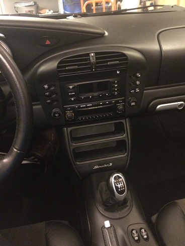
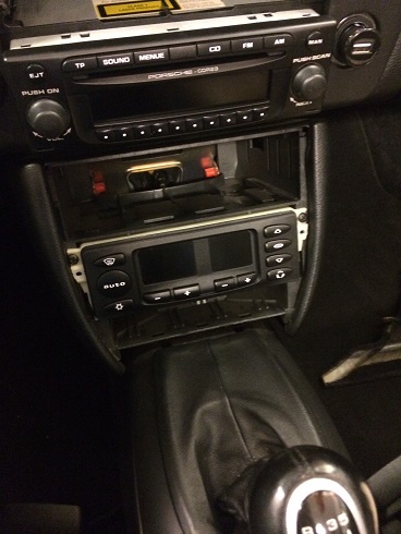
Before starting, AC on top followed by the CDR-23 and two storage compartments. Need to free up space on top.
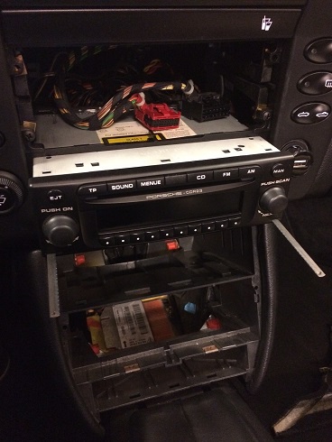
Prying the frame around AC with a plastic mini crowbar, releasing two screws and the connectors. The two storage compartments are pryed out starting with the upper one and then the lower one as they are mounted and hinged to each other that way.
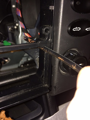
Since I dont have tools to release the CDR-23 i cut a mini jigsaw blade in two and use each end to bend the locking mechanism inside, one side at a time while gently pushing the unit out, which worked really well.
|

|

|
|
12-26-2015, 07:53 AM
|
#2
|
|
Crib
Join Date: May 2015
Location: Stockholm, Sweden
Posts: 80
|
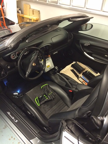
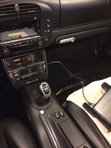
Working with the cab down makes it really pleasant and well lighted.
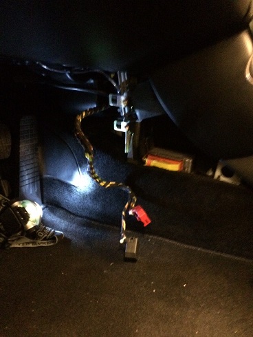
Releasing the side of the footwell towards the center console to be able to fish the AC cable with its two connectors down from its upper location. A bit tricky, but more time consuming than hard.
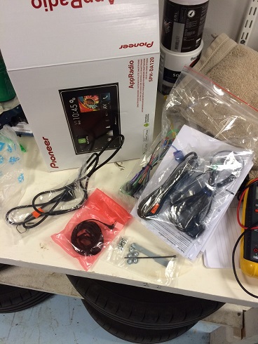
Unboxing of the new unit, unstructured task in the middle of the rest due to eagerness
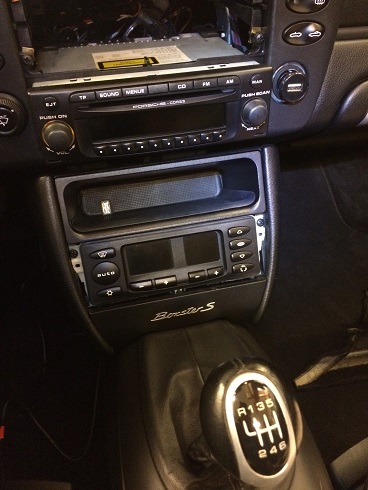
Back to the ongoing task, pressing the AC connectors and cabling through the hole in the back of the lower part of the center console to align with the bottom slot for its new placing.
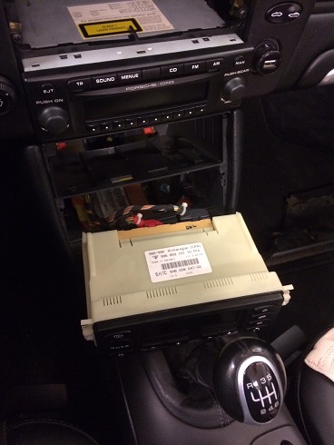
Reconnecting the AC control unit.
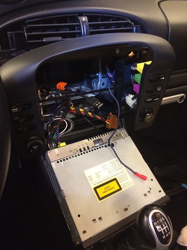
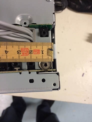
Sliding the unit into the slot and attaching the two black screw on the side. Note that holes for these screws only exist in the most upper or most bottom slots.
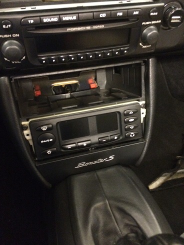
Putting back the bottom plastic part that had to come of while mounting the AC unit. Just gently pryed out and snapped back in again.
Last edited by Crib; 12-26-2015 at 08:05 AM.
|
|
|
|
|
12-26-2015, 07:55 AM
|
#3
|
|
Crib
Join Date: May 2015
Location: Stockholm, Sweden
Posts: 80
|
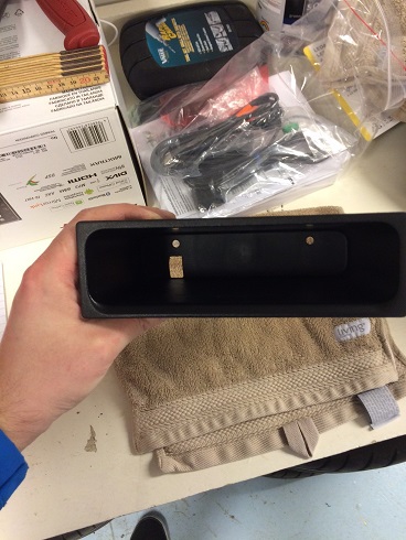
I want the USB connector for the Carplay to be in the remaining storage compartment so next task is to fit the female connector into that.
I mark the spot and drill holes around the edges...
...and cut it clean with a sharp knife. (The famous swedish Mora Knife )
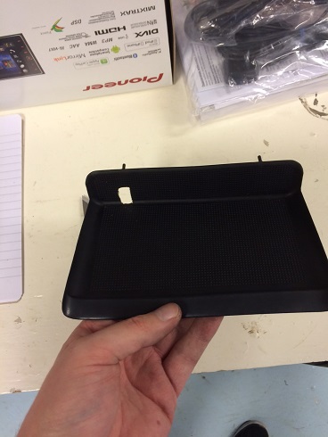
Adding a corresponding hole in the rubber insert.
Pressing the female part into the whole, snug fit.
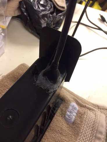
Fixating the connector with a major load of glue from the glue gun. Better safe than sorry, dont want this to losen up while connecting/disconnecting cables.
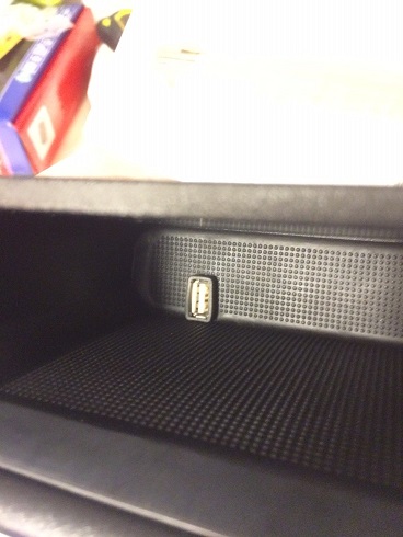
Treading the USB cable trough the hole into the back of the center console.
Pressing the storage compartment back into place. Found a 10cm (3 inch) black iphone cable that will be perfect in there (and also hide the whiteness of the connector).
|
|
|
|
|
12-26-2015, 07:56 AM
|
#4
|
|
Crib
Join Date: May 2015
Location: Stockholm, Sweden
Posts: 80
|
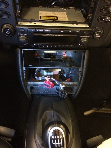
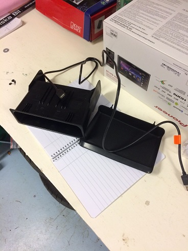
Treading the USB cable trough the back of the center console. It was easier than I'd thought and the cable just ran itself into the upper part to be fished out.
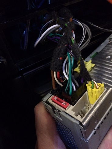
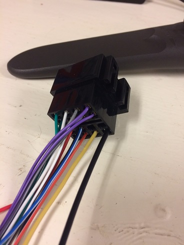
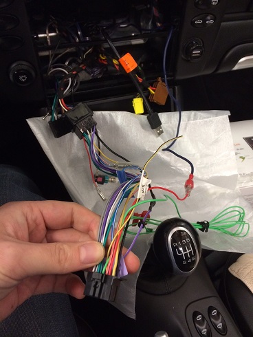
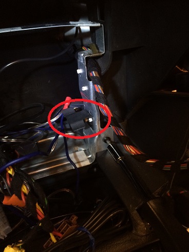
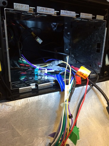
Next step will be cabling, cant seem to find the antitheft connector that I've seen in other posts. Perhaps this in the power connector for my model?
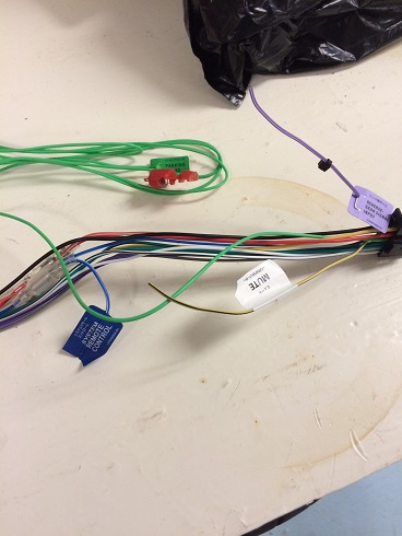
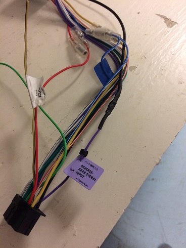
The adaptor for the new unit. Besides power and speaker cables it also features signal cables for a remote, mute, hand brake and rear gear for different functions on the unit.
Thats it for now, to be continued...
|
|
|
|
|
12-30-2015, 07:38 AM
|
#5
|
|
Crib
Join Date: May 2015
Location: Stockholm, Sweden
Posts: 80
|
Ok, so did some more today after having read up on the wiring for the Becker CDR23.
Besides the speakers, it turns out that the supply part of the connector from the car side is delivering Ground, 12V constant, Power antenna, Mute and Reverse gear.
So, no 12V switched/ACC... For this the CDR23 uses CAN data to recieve info of when ignition is turned. This is in the same socket as the line out signals.
So i need to find 12V switched elsewhere. Not the cigarette lighter in my car either it turns out as it is constant aswell.
After having gone through various options and spending quite some time with the multimeter I suddenly find an unattached cable, obviously non standard, that is 12V switched.
A previous owner has obviously put this there, most likely for another aftermarket HU in the past. It was made with an appropriate female crimp connector that makes it just too easy for me.
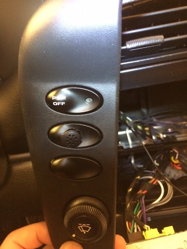
Next i mounted the microphone in a free dummy button slot. This will be used both for mobile handsfree and for Carplay voice navigation.
The CDR23 has a "Fakra" connection for the antenna cable. Something common for most VAG cars.
The new SPH-DA120 has the normal standard.
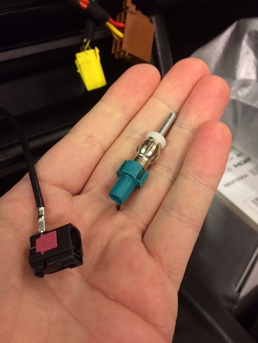
Found this adapter on Biltema (swedish store for auto parts and other useful crap) for the radio antenna cable.
|
|
|
|
|
12-30-2015, 07:52 AM
|
#6
|
|
Crib
Join Date: May 2015
Location: Stockholm, Sweden
Posts: 80
|
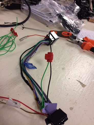
I prolong the reverse gear cable in the adapter...
...and attach it to the female connector with a pin stolen from another adapter. By this I dont have to tap in to any of the cars cables, now it will get it from the correct pin instead.
So plugging in the adapter and the 12V switched for a test run.
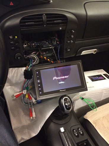
Turning the key and, voila!
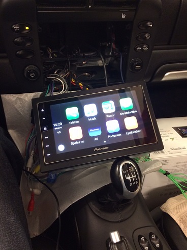
Plugging in the iphone in the USB port and Carplay just works.
Many of the settings on the HU are unavailable, but when grounding the parking brake signal they become active. So a permanent ground is the solution for the responsible me.
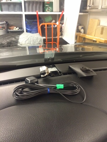
There is a GPS antenna for the HU aswell, used to better the signal. I opened this GPS cover under the windshield and found that the antenna would fit nicely in there. But getting the cable down to the HU looks like a pain.
Does anyone have experience in drawing the gps cable from its original position?
To be continued...
Last edited by Crib; 12-30-2015 at 08:00 AM.
|
|
|
|
|
12-30-2015, 08:10 AM
|
#7
|
|
Registered User
Join Date: Feb 2006
Location: Virginia
Posts: 1,755
|
I've run the GPS cable from the original position. It is not the easiest job, but it is doable.
Here's the process:
1. Gently lift up the defroster vent trim on both sides. This will give you access to two small screws that hold the IR carrier assembly in place. Be gentle with the defroster trim because it is probably brittle from years of sun exposure. You don't need to totally remove it, just prop it up out of the way.
2. I used this screw driver kit from Harbor Freight: 8 Piece Right Angle Screwdriver If I recall correctly, you need to use the Torx bit in the kit. I actually held the bit between my fingers. You may want to take precautions to prevent the screws from falling into the defroster vents. I didn't drop mine, but you are working in an awkward location and it would be easy to drop them.
3. Once you have the carrier out of the way, run a straightened coat hanger or a piece of string down the dash. (You will need to have the AC vents out of the way to make this easier. Attach the end of your GPS antenna that goes to the back of the head unit to the string and pull it down through back of the dash. Look carefully at how the wire needs to travel through the IR sensor area.
Good luck.
__________________
2000 Arctic Silver/Black, Hard Top, On Board Computer
PNP Rear Speakers, HAES 6-Channel Amp, Avic Z140BH,
Painted Bumperettes, 2004 (OEM) Top, Homelink integrated in dash with Targa switch, 997 Shifter, Carrera Gauge Cluster with silver gauge faces, heated 997 adaptive sports seats, Litronics, silver console
|

|
|
|
01-01-2016, 07:44 AM
|
#8
|
|
Crib
Join Date: May 2015
Location: Stockholm, Sweden
Posts: 80
|
Thanks for the hints Kevin, much appreciated!
Gently prying the cover away and releasing the connector for the alarm light.
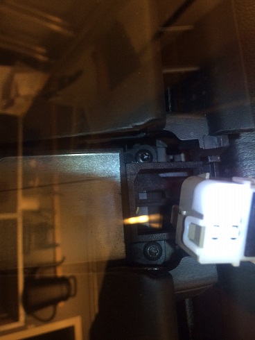
These are the two torx Kevin was talking about, that needs to be released in order to release the holder and get the GPS cable correctly routed.
Was a bit worried about having an angled screwdriver and dropping the screws so instead I did what i think Porsche could have prepared from the beginning, a slice in the plastic for the connector, drawing the cable that way, without relasing anything. The slice needs to be on the right side since the connector is not as deep on that side.
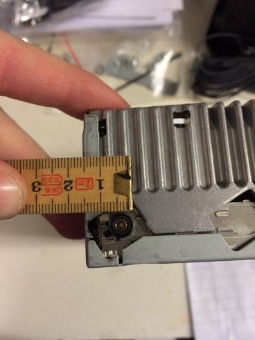
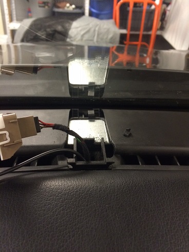
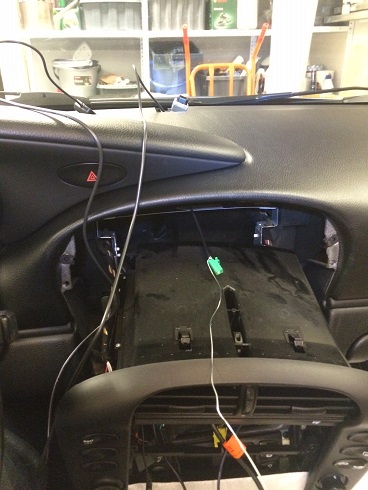
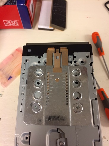
The AC vents needs to come out in order to fish the cable, which was a bit troubling since the manual pictures are really unclear. I dont know if this differs between models but in my car there were two metal parts with saw teeth that needed to be bent downwards from from inside the vent with a little flat screwdriver, contrary to what i found the the internet were there seems to be models with one of these things in the middle and further back.
Close-up of one of the metal thing with saw teeth.
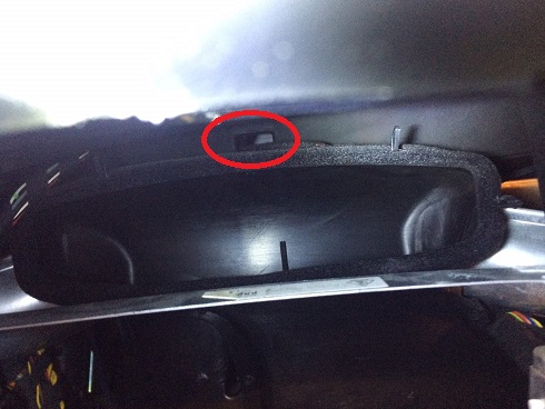
With the AC vent box taken out, this hole leads up to the GPS position.
With a thicker metal string it was actually quite easy to fish the cable from top and down.
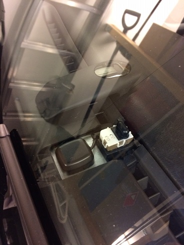
The GPS puck has magnets underneath that attached nicely to the standard metal plate in the position. The connector jacks in nicely with the new neighboring cable underneath. On with the cover and no evidence left behind
|
|
|
|
|
01-01-2016, 10:48 PM
|
#9
|
|
Registered User
Join Date: Feb 2006
Location: Virginia
Posts: 1,755
|
Quote:
Originally Posted by Crib

Was a bit worried about having an angled screwdriver and dropping the screws so instead I did what i think Porsche could have prepared from the beginning, a slice in the plastic for the connector, drawing the cable that way, without releasing anything. The slice needs to be on the right side since the connector is not as deep on that side. |
Nice idea - I wish I had thought of that. It would have saved me from a tedious task.
__________________
2000 Arctic Silver/Black, Hard Top, On Board Computer
PNP Rear Speakers, HAES 6-Channel Amp, Avic Z140BH,
Painted Bumperettes, 2004 (OEM) Top, Homelink integrated in dash with Targa switch, 997 Shifter, Carrera Gauge Cluster with silver gauge faces, heated 997 adaptive sports seats, Litronics, silver console
|
|
|
|
|
01-01-2016, 12:15 PM
|
#10
|
|
Registered User
Join Date: Jun 2014
Location: LB, Germany
Posts: 1,526
|
I would recommend to install microphones on top of the steering wheel cover to get a good voice quality.
Regards, Markus
|
|
|
|
|
01-01-2016, 06:28 PM
|
#11
|
|
IronDeadPool
Join Date: Oct 2015
Location: Toronto
Posts: 125
|
Nice write up!
__________________
P O R S C H E . B O X S T E R
Project IronDeadPool
|
|
|
|
|
01-02-2016, 05:36 AM
|
#12
|
|
Registered User
Join Date: Oct 2015
Location: Pittsburgh
Posts: 99
|
I am confused, I thought cars equipped with the cdr23 stereo had the M.O.S.T. (fiber) and that a plug and play solution was unavailable. Are you still using factory amp and speakers?
|
|
|
|
|
01-02-2016, 01:48 PM
|
#13
|
|
Crib
Join Date: May 2015
Location: Stockholm, Sweden
Posts: 80
|
To be honest I was a bit confused myself to see a connector with the lineouts being plugged in, but my guess was that it was needed for the ignition can data signal.
But seeing the extra added switched 12V cable and that the speaker cables being directly connected to the cdr-23 makes one believe that an earlier owner has done some mods and restored it back before selling the car.
In short: I'm not using factory amp, and the speakers are (and will be) directly plugged into HU.
|
|
|
|
|
01-02-2016, 02:00 PM
|
#14
|
|
Registered User
Join Date: Jun 2014
Location: LB, Germany
Posts: 1,526
|
If the car has no Bose sound system or "Klangpaket" with an additional amp the speakers are always connected to the HU. But these cars have only speakers in the dash and no speakers in the doors and they don't have an amp in the front trunk.
Regards, Markus
Last edited by Smallblock454; 01-02-2016 at 02:04 PM.
|
|
|
|
|
01-03-2016, 09:52 AM
|
#15
|
|
Crib
Join Date: May 2015
Location: Stockholm, Sweden
Posts: 80
|
It has no amp, but it has aftermarket speakers in the doors. A future project will be to change both door and dashboard speakers to something better sounding.
|
|
|
|
|
01-06-2016, 11:42 AM
|
#16
|
|
Crib
Join Date: May 2015
Location: Stockholm, Sweden
Posts: 80
|
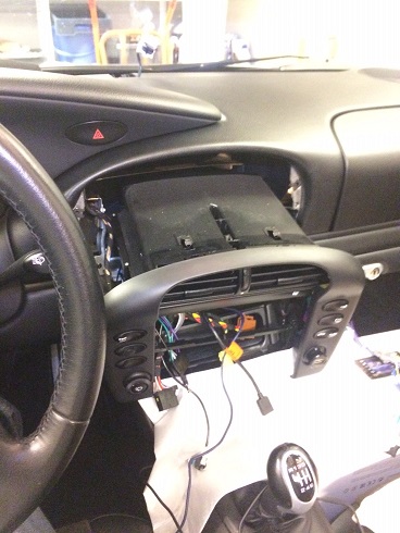
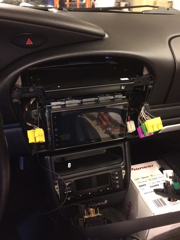
OK, so here is the final part.
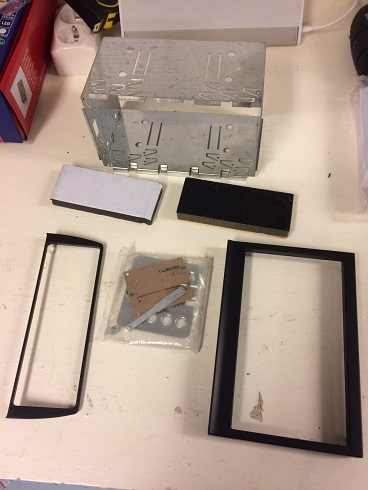
Got the installation kit i've ordered containing a mounting cage and two bezels for the new rounded AC slot and one for the HU since the space is larger than regular double din.
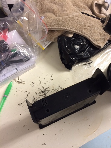
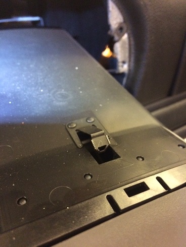
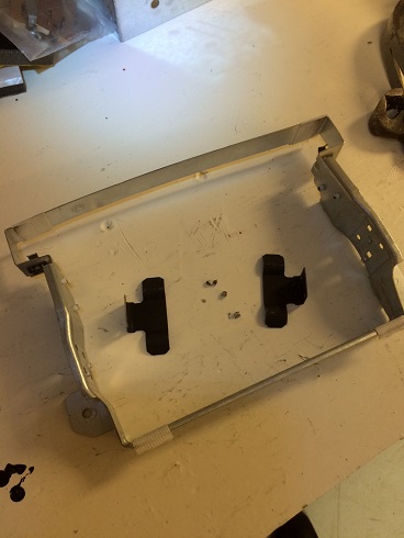
The plastic bar in the middle of the upper compartment needs to be removed. I saw it in line with the frame, meaning in the middle of the screw holes.
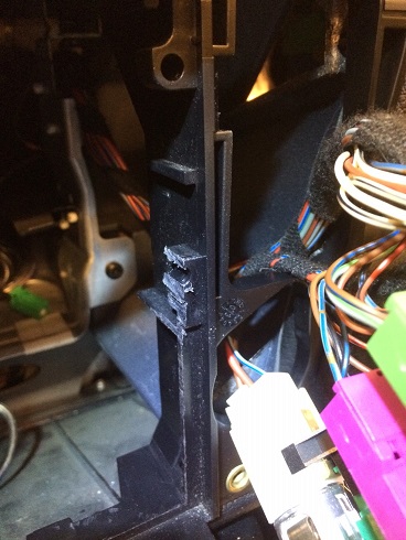
The cut does not need to be perfect as long as it is out of the way of the cage.
This seems to differ between models from what I've read, but my car has metal guides on either side that also needs to come of. The metal frame is released with two torx screws.
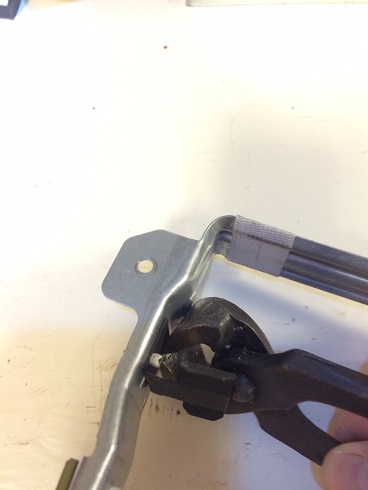
The metal guides are attached with rivets, that can be pinched of from the inside.
With the rivet heads gone the metal guides can be pryed of with a screwdriver.
Attached the locking mechanism from the kit I ordered on the HU. Need to experiment a bit with the length of the mounting to get the HU correctly aligned with the console.
Last edited by Crib; 01-06-2016 at 11:48 AM.
|
|
|
|
|
01-06-2016, 11:47 AM
|
#17
|
|
Crib
Join Date: May 2015
Location: Stockholm, Sweden
Posts: 80
|
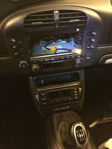
Attaching the cage in the upper compartment.
Connected cables and pressing in the HU until locked.
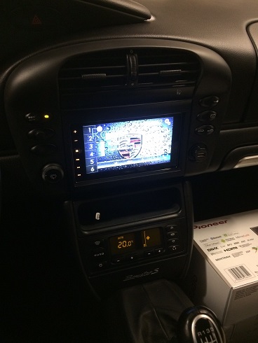
Pressing the two new bezels in place.
Changed the color scheme to match the cars orange lighting, and threw some random Porsche pics on a usb stick for testing. Three different modes can have different pics.
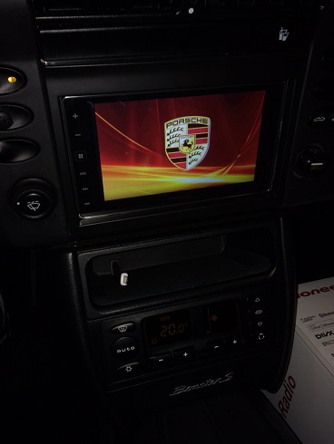
Splash screen on startup.
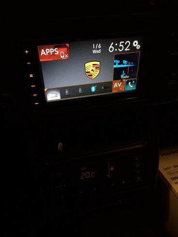
Main screen.
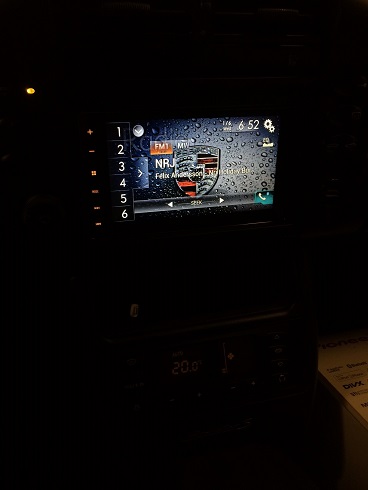
Radio mode
So, thats it. I'm very satisfied with the result
|
|
|
|
|
01-06-2016, 01:50 PM
|
#18
|
|
New Porsche Fan
Join Date: Sep 2015
Location: Atlanta
Posts: 122
|
Very nice...I'm about to do the same thing soon.
__________________
2001 Black Boxster
2004 Red Vespa 150cc
2006 Black Maserati QP
2008 Black VW Eos
2010 Charcoal Ford Flex
|
|
|
|
|
01-01-2018, 04:11 PM
|
#19
|
|
Roboxster
Join Date: Jan 2018
Location: Gothenburg, Sweden
Posts: 7
|
Thanks for a great post!
Doing a similar thing with my 03 S. But with a Pioneer SPH-DA230DAB,
and since the car has the Bose amp and sub with MOST I am buying an active adapter wich will keeping all features except fader.
Am still considering using a denon amp I have, but uncertain if it can manage the low ohm speakers...
Tack igen från andra sidan Sverige :-)
|
|
|
|
|
01-06-2018, 08:34 AM
|
#20
|
|
Registered User
Join Date: Aug 2015
Location: Stockholm, Sweden
Posts: 282
|
Snyggt jobbat!
I think I'll use this as instructions on how to get my GPS antenna in the right place. 
|
|
|
|
 Posting Rules
|
You may not post new threads
You may not post replies
You may not post attachments
You may not edit your posts
HTML code is On
|
|
|
All times are GMT -8. The time now is 08:05 PM.
| |


 Porsche Boxster
 Hybrid Mode


