Location: Montreal, QC. (currently expat to Shanghai)
Posts: 3,249
Quote:
Originally Posted by 911monty
This thread is fantastic! Not often you get to see the inner workings of a master artist at work. Guess a Cheese Toast will have to do...
Do not get hypnotized by these modern and expansive software/tools man. The "true" masters are those who fabricate with their hands, and using tools that everybody has. If you want to know my version of true (genuine) ingenuity!
But thanks for the compliment, well received!
Quote:
Originally Posted by Anker
Bring the Task Manager up and check if the Windows Antimalware Executable is hogging the CPU. If it is, google on how to prevent it from doing that. I had exactly the same issue and had to take care of it.
Sorted. It would have been a tad more helpful for me if the main-board would have beep'ed letting me know what it was. My neighbor's son disconnected the E drive and all came back to normal. The HDD was an old style WD and basically died. Not sure why this HDD was left in there anyway, been using SSD since a few years already. Thanks for trying to help bud, too kind
Quote:
Originally Posted by Troy.Boxster
Damn you Fred! I'll take four.
haha Troy! ah for you its local pickup only. Always good to hear from you brother
__________________
______________________________
'97 Boxster base model 2.5L, Guards Red/Tan leather, with a new but old Alpine am/fm radio.
Location: Montreal, QC. (currently expat to Shanghai)
Posts: 3,249
Wheel Hub Adapter (start)
The part below will be the wheel hub adapter.
It threads & secure itself inside of the cap and meant to clamp the whole cap assembly onto the hub geometry of the wheel. As you can see I am using the traditional clamping style that, well, Porsche and many other automakers are using already. Im guessing there is a reason for this widely used concept so no point going all creative RE hooks, clips, or new ways to get this to clamp. Lets stay focus lolll
I wont lie, Ive already tough up this part quite a while ago. Often Ive heard complains about how difficult it was to install the previous CGT style caps and many said it got to be a better way. So there, Ill finally comply with this and provide in the best of my capacity.
The material well be using for this part alone is Acetal (Polyoxymethylene, or Delrin if you prefer). Acetal is possibly ranking Top 1 in its group of engineering plastics and for many reasons (you can read about it). Not exactly cheap, in fact The Most Expansive in its class, but at least well be 100% sure that the part will last for minimum half a century and perform in literally any environments. E.g. whether you roll my cap in Alaska at below 40deg Celsius or Texas at above 40, The Great Center Cap is going to stay on your wheel and perform its task without any complains.
I personally love Acetal because it is magical to machine. If you are familiar with its thermal expansion behavior, you can achieve tolerances of 1~5micron on this thing without much efforts (not joking). Something Ill need to do for the matting of the threads with those of the cap, youll see why later.
Ill soon explain the method Ill be using to thread lock Acetal with the aluminum cap using its thermal expansion properties. Thats right; thermal expansion is occasionally an advantage for engineers, not all negative!
Nuff blah, its all about visuals (and Cheese Toasts in between)!
And off to the part validation (CAE). Lot of work there :/ The ring in front of the adapter represent the exact same geometry of the Porsche wheel hub. Same shape, size and tolerance (0.05mm) and used for non-linear clamping analysis.
__________________
______________________________
'97 Boxster base model 2.5L, Guards Red/Tan leather, with a new but old Alpine am/fm radio.
Location: Montreal, QC. (currently expat to Shanghai)
Posts: 3,249
CAE and part validation
Acetal is “snappy”.
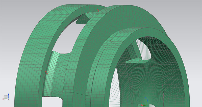
Here I’ll share with you validation procedures that the part will undergo. In general terms, we need to ensure a few things for this to work. 1) Ensuring that the part does not exceed (in any ways) the Ultimate Tensile Strength(110Mpa) anywhere in the clamping process i.e the ultimate TS is when the part shatters in little pieces, or the moment when you get mad at me loll. We also need to ensure that it stays below its Yield Strength (64 Mpa) when in operation. We don’t want the part to be living under excessive stress during all of its life. Within the range is perfectly fine, but not above!
Lastly, it need to provide a good clamping pressure so when the wheel rotate and X and Z velocities changes, the cap remain where it should. Keeping a pressure above 100Mpa is the target here so watch your fingers when you snap them into place, it’s going to hurt-a-little if you get your skin trapped between the wheel and the cap Although, for a light 77grams cap, I think that 50 would be more than sufficient – but let’s not take any chances!
Side note: for anyone familiar with CAE, I am solving this with SOL 601,106 Advanced Nonlinear Statics (using a 0.2 as coefficient of friction, 2D CQUAD4 mesh and a RBE2 connector for the enforced displacement). Nastran 11 Solvers, what else better
^ Not 100% completed but going into the right direction! Nasty work I tell ya but still fun to do. Sometimes I think my fellow Chinese friends have the right way of doing things = "looks good, then its okay lolll"
__________________
______________________________
'97 Boxster base model 2.5L, Guards Red/Tan leather, with a new but old Alpine am/fm radio.
Last edited by Nine8Six; 01-21-2017 at 11:23 PM.
Reason: This forum resize pic down to 640px, hate it :/
Location: Montreal, QC. (currently expat to Shanghai)
Posts: 3,249
CAE and upcoming Multiphysics Simulation
Decided to become a VJ for one day loll
Did this vid to show the ‘behind the scene’ of CAE and how design (or feature) changes are validated. In this video we’ll be lowering the height of the clip and wall by -0.5mm. We’ll then clone the solution and see how stresses compare to the design changes.
When I say ‘nasty job (but fun)’ I really meant that. It can take quite a bit of time to come up with a proven concept – weeks sometime.
Next: I'll be showing how to balance a part assembly using Multiphysics Simulation tools and sensors. Think some of you will love that episode. I'll try to vid those over youtube for you guys to see.
__________________
______________________________
'97 Boxster base model 2.5L, Guards Red/Tan leather, with a new but old Alpine am/fm radio.
Location: Montreal, QC. (currently expat to Shanghai)
Posts: 3,249
Quote:
Originally Posted by jaykay
Jeez Fredric ......did you make them integrate a CAD station in your hostpital bed
Dude I think its what they put in the cheese these days :/
Already at balancing this assembly Jay. Doing the 1800RPM(223km/hr) currently. Hopefully be done with counter-weighting the center/badge by tomorrow so I can (finally) send this to CAM. I'm actually really eager to see them myself.
Secret: good tools man... makes for an easy job. Prototypes are always spot on
__________________
______________________________
'97 Boxster base model 2.5L, Guards Red/Tan leather, with a new but old Alpine am/fm radio.
Holy Cow!!! Just caught this thread. Two questions, when will they be ready and how much? Oh heck, forget how much just when will they be ready? Great work, absolutely wonderful...
Fred congrats on getting better keep healing and moving forward ! I may have missed it but how are you adding color to the parts ? Does the raw material already contain the color ? Or are they going to be painted ? And what colors will be available ? I think " the beast " needs a set of these but I'll have to figure out the color . Thanks for what you add to the forum and community .
__________________
2002 Boxster S Arctic Silver with black top with glass window and black leather interior. Jake Raby 3.6 SS ( the beast ) with IMS Solution. 996 GT3 front bumper , GT3 rocker covers and GT3TEK rear diffuser and Joe Toth composites rear ducktail spoiler .
Location: Montreal, QC. (currently expat to Shanghai)
Posts: 3,249
Quote:
Originally Posted by kjc2050
Yikes. Beautiful!! Fred, your work is amazing.
Kevin, too kind brother
Quote:
Originally Posted by steved0x
Holy crap I want these!!!
Me too, I think lolll Very humble piece of kit from the wheel/cap visuals that came out yesterday.
Quote:
Originally Posted by PaulE
A touch of red on my seal gray car with silver wheels will look nice I think!
Same here. Boxster have the blue CGT caps on since 3 years, time for red I think
Quote:
Originally Posted by jakeru
Nice work - Fred - love seeing your techniques!
Thanks bud! Not done, far from it actually. Subscribe if you haven't done so because there is so much more coming. I'll soon be starting the CAM work, fixtures, sourcing the correct materials for prototyping, we'll machine this using the High Speed machining center (Siemens controllers), We'll also laser-mark this cap with something sexy, etc etc. Planing to hit the shop floor in a week! Plenty of fun to come, stay tuned
Quote:
Originally Posted by Jgkram
Holy Cow!!! Just caught this thread. Two questions, when will they be ready and how much? Oh heck, forget how much just when will they be ready? Great work, absolutely wonderful...
Too bad folks doesn't do the DYI section of the forum as much as the General one. No price yet, let's machine all this together, get quotes on materials and that will eventually define the end price. So far we are looking at a pretty cheap-to-manufacture part... I'll try my best to keep it that.
Not hidding anything, everything is real here so what I pay for my caps is pretty much what you'll also pay for yours
Quote:
Originally Posted by rfuerst911sc
Fred congrats on getting better keep healing and moving forward ! I may have missed it but how are you adding color to the parts ?
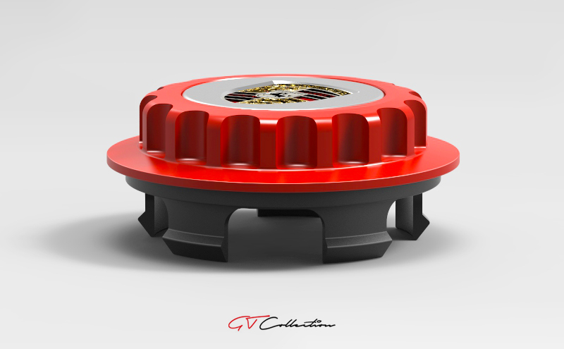
Thanks Rick, yup getting better by the week. If I don't get hit by a lightning (i.e my type of luck recently) I should be back to 99% same in less than 12 months. Wish me luck man lolll The main cap will be 6061 aluminum and anodized in the color of your choice (gun metal, red, blue, black, etc). The center where the P shield is should ideally remain silver (clear anodized). Fully custom mate, so if the beast needs something unique I'll be 100% able to provide that for you bud
__________________
______________________________
'97 Boxster base model 2.5L, Guards Red/Tan leather, with a new but old Alpine am/fm radio.
Location: Montreal, QC. (currently expat to Shanghai)
Posts: 3,249
Multiphysics Simulation - Assembly Balancing
Just a few visuals on the assembly balancing and a video showing my highly guarded & secret Newton's Cradle below. Run the vid half way to see the motion of the center cap. Just quick visuals for you guys, sorry, not the full thing (man, this is all time consuming this pic/vid/encoding thing loll).
Simple you may think but incurably powerful. Pure physics; 60+ years old solvers (NASA(nastran), Recurdyn, Adams, etc). Its all about the quality of the solvers really.
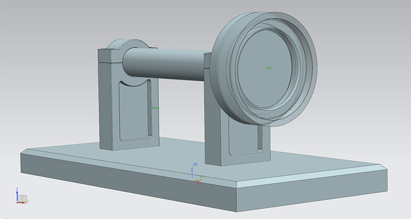
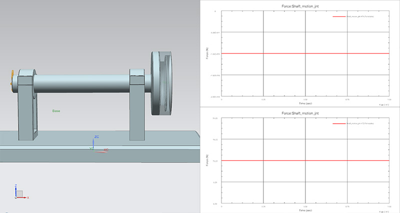
^ Here you can see the assembly I use for balancing rotary parts. It’s a base having a shaft rotating in the X axis. Not specific to the center cap I am doing now, I’ve actually used this for quite a few other parts successfully (custom spacers, CNC tool holders, custom rotary chucks soft jaws, center caps, etc etc).
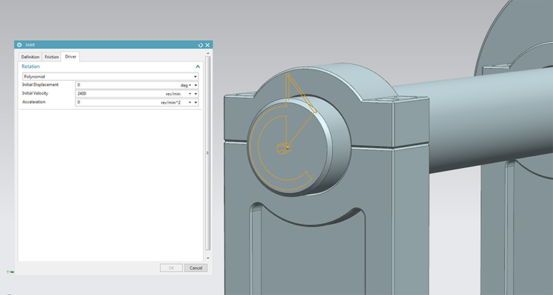
^ The shaft uses a driver (motor) set at 2,400RPM for this test. You can however set this to pretty much anything between 0 ~ 999,999,999rev/sec. Here we are testing vibration on a Porsche wheel with a diameter of 660MM (26"), or a circumference of 2073mm (660*PI). In velocity, and if spun at 2,400RPM, this gives us 82,938mm/sec (or 298km/h). So the target here is to rate the Great Center Cap for speed of 300Km/h without any sort of vibration.
^ First thing first, calibrating the shaft coupled with the Porsche wheel hub (translucent part; right end side). We should be getting a flat line e.g. no changes in force magnitude anywhere = zero vibration.
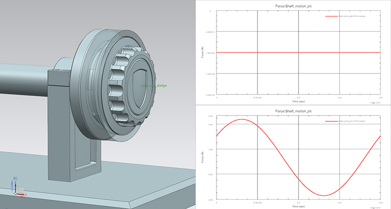
^ With all the parts of the assembly inserted into the wheel hub, we are getting a vibration in the Z axis (i.e. up/down). So by deactivating each part of the assembly, it is easy to figure out which part is causing the wiggle. In the case of this assembly, the Center holding the P badge is the culprit.
^ To make things a bit easier visually, we slow down the motion solver to 1 (one) rotation only so we can clearly see the vibration curve. Still rotating @2,400RPM (40rev/sec) however the time steps drops from 1 sec down to 0.025sec (e.g 1sec / 40rev per sec). So 1 full revolution only here. Easier to see than the above graph!
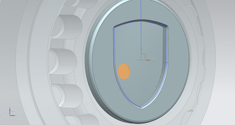
^ Now having found the culprit, you need to go back to the drawing board and counter-weight the part. In this case material had to be removed (orange). Once the center of mass gets back to zero, you re-import the part and re-solve the motion.
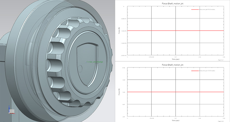
And BINGO!
^ As you can see, we are now getting 100% flat line per revolution (still at 2,400RPM). The badge is set to 50% transparent so you can see where the little pocket is located.
At the manufacturing stage, a very small pocket will need to be machined inside the area where the P badge goes and all will go back in perfect balance!
And that is how we design rotating parts and balance them using Multiphysics Motion Simulation ladies and gent. Fairly elementary and simple lollll
VIDEO
You'll see my Newton's Cradle in there (not a toy!). Again; incredibly powerful. CAE allows us to export Flexible Bodies (e.g. response dynamics) and import those inside Motion Sim. That is how we get table field of data for various materials used for creating parts (forces, damping, etc). This data is then used down the line for crash/impact analysis, fatigue analysis, stuff like that. Could be wrong but I think every engineers have a Newton's Cradle modeled (can't be found anywhere, you got to make your own and mine's not for sale loll)
__________________
______________________________
'97 Boxster base model 2.5L, Guards Red/Tan leather, with a new but old Alpine am/fm radio.
Now that's very counter-intuitive to me that on a perfectly symmetric looking object, that the lightening relief would be positioned off the line of symmetry. Any explanation as to why, Fred?
Also, I find it interesting that you've modeled a balancing apparatus. Wouldn't it be just as easy to assume the piece is sitting there in space and rotating by some strictly defined (assumed unmoveable) axis? I suppose with your method, you could model flexibility and oscillations of the testing jig, but I'm not sure why that would be useful, unless you were doing real-world testing on the same exact jig and wanted to somehow model very similar predicted results. At some point, the model needs to assume things are fixed. Would this simulation assume the base feet of the testing jig are fixed?
I remember getting some unversity mechanical engineering grad student to help do some FEA simulation work on designing a lightened version of wheel centers for an autocross race car I was running. This was at least 10 years ago, so the tools were a bit more rudimentary to what you seem to have access to. I don't remember using using any solvers, but rather, just manually iterated the design a few times until we were happy. The machined weight of those wheel center came out just as predicted! Very cool and memorable experience for me. So thanks for sharing your fascinating techniques.


![Custom Center Caps for Porsche Wheel [from CAD, prototyping to finish]](/forums/iconimages/diy-project-guides/custom-center-caps-porsche-wheel-%5B-cad-prototyping-finish%5D_ltr.gif)


 Although, for a light 77grams cap, I think that 50 would be more than sufficient – but let’s not take any chances!
 Boxster S
 Genesis 3.8


 2004 Porsche Boxster S
 2004 Porsche 996 Targa
 Linear Mode


