Go Back   986 Forum - The Community for Porsche Boxster & Cayman Owners > Porsche Boxster & Cayman Forums > Boxster General Discussions

Post Reply
 
LinkBack Thread Tools Display Modes
Old 07-14-2024, 07:56 AM   #1
Registered Member
 
Join Date: Sep 2022
Location: Massachusetts
Posts: 16
Convertable Roof doesn't work

Unrelated to my clutch issues, I took the hardtop off of the car when it came back from the shop, and tried to put the roof up.

Nothing. The light on the dash button didn't come on. If I listened carefully, I could hear a click and a hum from behind the dash, but nothing happened.

So I started with the big convertible relay under the driver's side dash.


Hmmm... That doesn't look promising.


Nope! This does not look healthy.


Last edited by jluetjen; 07-14-2024 at 07:59 AM.
jluetjen is offline   Reply With Quote
Old 07-26-2024, 02:51 PM   #2
Registered Member
 
Join Date: Sep 2022
Location: Massachusetts
Posts: 16
Duh! This post might be more helpful if I learned how to spell Convertible correctly!
jluetjen is offline   Reply With Quote
Old 07-26-2024, 02:55 PM   #3
Registered Member
 
Join Date: Sep 2022
Location: Massachusetts
Posts: 16
Hmm. I'm trying to figure out which portion of the circuit went up in smoke.

The module pins are labeled pins 11-29. The Bentley manual's electrical diagram is labeled A1-A8 and B1-B9.

I'm guessing based on the pin count that the burnt section is the B-half of the module.

Doing a quick search on "NEC EN2-2H3" that can be seen on the large component next to the burn marks, (and the bubbled plastic cover!) and it reveals that the component is a "Automotive Twin Relay" with the function of "Twin relay for motor and solenoid reversible control". Yup, that's the relay in the schematic on the B-side of the controller. That looks about right.

The connections on that side of the relay are:
* A1 on the convertible top motor
* A2 on the convertible top motor
* Cluster (the dash seems to be working fine)
* Fuse B6 (Already confirmed as good)
* The alarm (which seems to be working OK)
* Fuse D3 (also confirmed as good)
* CP 1 GP 3. (???)

I guess I'll need to see if power is going out to the motor successfully.

Last edited by jluetjen; 07-26-2024 at 04:09 PM.
jluetjen is offline   Reply With Quote
Old 07-28-2024, 01:18 PM   #4
Registered Member
 
Join Date: Sep 2022
Location: Massachusetts
Posts: 16
I just did some more troubleshooting and noticed that the microswitch next to the convertible motor is missing.


That would be the black, L-shaped piece in the upper left corner of the bracket in this image.

That might be meaningful...
jluetjen is offline   Reply With Quote
Old 08-01-2024, 10:41 AM   #5
New Boxster S owner
 
Join Date: Jun 2023
Location: AL
Posts: 25
I don't think later years have a microswitch by the motor like that. What year is your car?
madtown986 is offline   Reply With Quote
Old 08-05-2024, 03:53 PM   #6
Registered Member
 
Join Date: Sep 2022
Location: Massachusetts
Posts: 16
My car is a 2002, and that may explain my confusion. On the left is what I took off of the car (I've already moved the grommets over to the new unit on the right).


As you point out -- I don't see any switch. The confusing part is that at one time I found a broken version of that black rocker arm shown on the new stich on the right. I could never figure out what it came from.

But when I look at the connections in the car, I only see a single plug, which seems to be for the motor.


What you describe would explain why!

Looking at the parts drawing though shows both a bracket with a switch and a bracket without the switch, but with no years marked next to them. The motor on the other hand seems to have changed part numbers between the 2003 and the 2004 model years.

Did the switch get moved to a different location? Or was it just omitted?

So I looked at our host's site for the 2003 and earlier electric motor for the convertible top and see... "986-624-117-00 superseded to 986-624-117-01 (ELECTRIC MOTOR)"

The 986-624-117-01 is the part number for the 2004 and later cars.

Last edited by jluetjen; 08-05-2024 at 04:13 PM.
jluetjen is offline   Reply With Quote
Old 08-06-2024, 05:02 AM   #7
Registered User
 
Join Date: Jul 2024
Location: Western Europe
Posts: 36
I recommend checking these points before you test it with a new relay...

TROUBLESHOOTING ON THE RELAY CONTROLLER
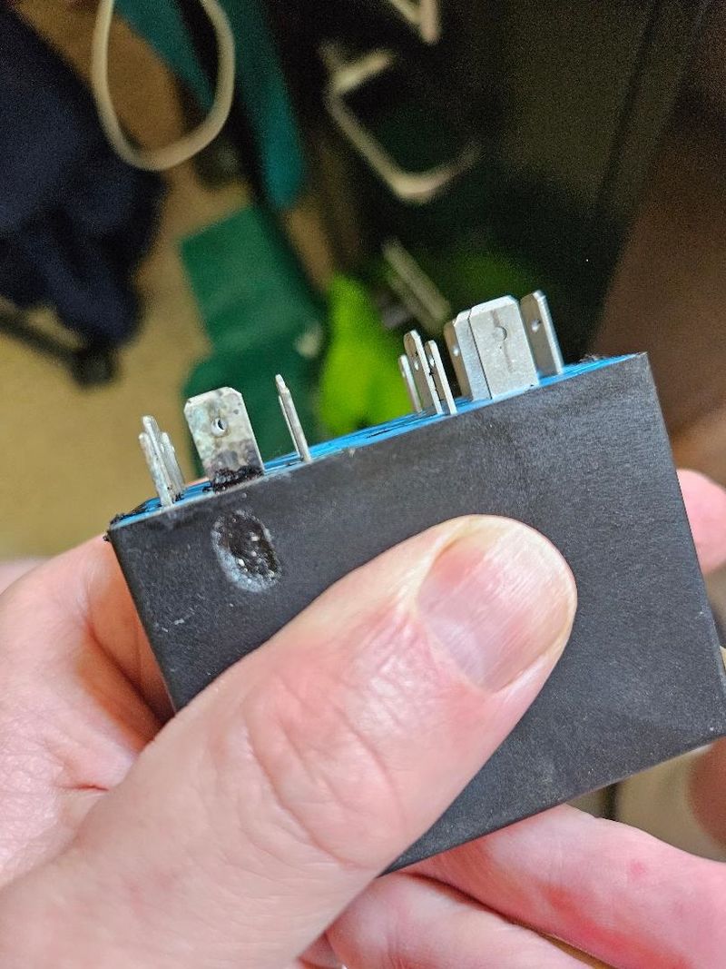
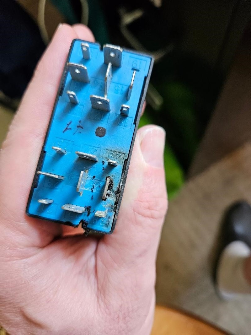
Note: Control relay disconnected. The terminal designation on the relay (Fig. 596_97) is from the underside of the control relay.
1. connect the measuring device (voltmeter) to terminal 22 (earth) and terminal 23 (plus 30) on the relay plate. Display = battery voltage
2. connect the measuring device to terminal 22 (earth) and terminal 26. Switch on the ignition. Display = battery voltage
3. connect the measuring device to terminal 23 (plus) and terminal 15 (handbrake applied). Display = battery voltage
4. connect the measuring device to terminal 23 and terminal 16 (close soft top button). Press close button. Display = battery voltage
5. connect the measuring device to terminals 23 and 17 (open soft top button). Press the open button. Display = battery voltage
6. convertible top locked . Connect measuring device to terminal 23 and terminal 14 (microswitch wind frame). Display = battery voltage
7. convertible top locked . Connect the measuring device to terminals 23 and 29 (microswitch B-pillar). Display = battery voltage
8. top unlocked. Connect the measuring device to terminals 23 and 13 (microswitch closed, soft top compartment lid VDKD open). Display = battery voltage
9. convertible top unlocked . Connect the measuring device to terminal 23 and terminal 19 (microswitch wind frame). Display = battery voltage
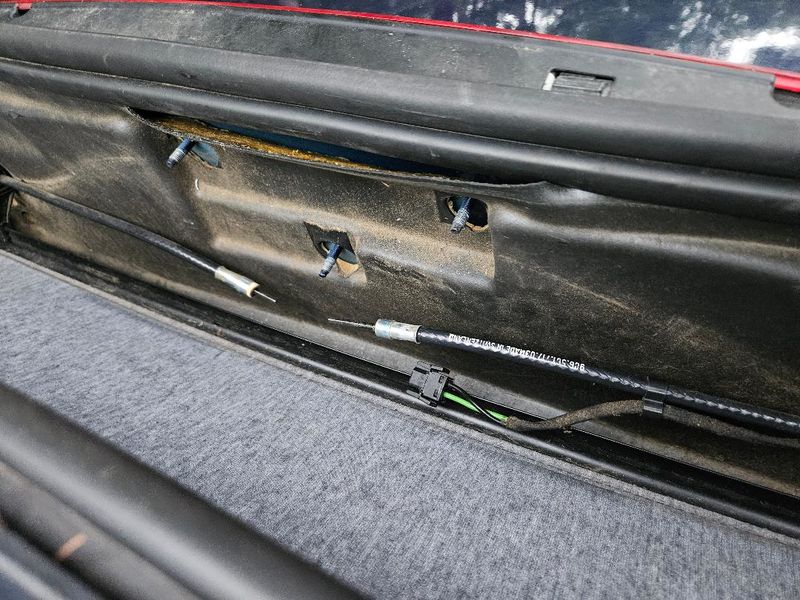
Connect control relay to relay carrier. Open the soft top compartment lid and disconnect the electrical plug connection on the drive motor-top drive.
10. connect the positive of measuring device to terminal 1 (black cable) and the negative of measuring device to terminal 4 (green cable). Kl. 2 and Kl.
11. connect the positive of measuring device to terminal 4 (green cable) and the negative of measuring device to terminal 1 (black cable). Bridge terminals 2 and 3 with an auxiliary cable. Switch on the ignition and press the "Close" button. Display = battery voltage

Btw, 
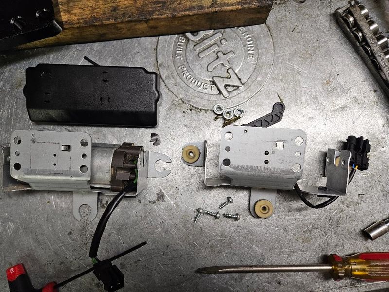
afaik from 2000 onwards there are only two microswitches, one in the lock and the other in the planetary gearbox. No microswitch on the bracket of the motor.

Last edited by 997_986; 08-06-2024 at 05:12 AM. Reason: Adding
997_986 is offline   Reply With Quote
Old 08-11-2024, 12:59 PM   #8
Registered Member
 
Join Date: Sep 2022
Location: Massachusetts
Posts: 16
I got as far as step-8. It looks like my microswitch is bad. This video was helpful in troubleshooting and removing the switch. We'll see what happens once I get the new switch in later this week.

jluetjen is offline   Reply With Quote
Post Reply


Posting Rules
You may not post new threads
You may not post replies
You may not post attachments
You may not edit your posts

BB code is On
Smilies are On
[IMG] code is On
HTML code is On
Trackbacks are On
Pingbacks are On
Refbacks are On


All times are GMT -8. The time now is 05:23 PM.


Powered by vBulletin® Version 3.8.7
Copyright ©2000 - 2024, vBulletin Solutions, Inc.
Content Relevant URLs by vBSEO 3.6.0
Copyright 2024 Pelican Parts, LLC - Posts may be archived for display on the Pelican Parts Website -    DMCA Registered Agent Contact Page