 08-26-2019, 04:57 AM
|
#1
|
|
Registered User
Join Date: Sep 2013
Location: uk
Posts: 19
|
Brake Booster Vacuum leak
I have a problem, wonder if anyone can help.
Car went to garage to have power steering pump changed. short time afterwards CEL came on. I have a durametric and recon the symptoms related to vacuum line leak. Checked around area of pump and spraying carb cleaner near this area engine revs pick up. Can also hear the sucking noise from the valve at the back of the intake manifold, the brake booster take off point.
I also found a horseshoe shaped grey clip in the well where the hood folds into, which clearly has not gone back somewhere during the work that was done previously.
So my question, is the piece marked part 24 on the Porsche vacuum diagram a small grey horseshoe fitting and if so does it just clip on? If not is there an o ring that can be changed in the actual fitting?
Many thanks
Ian
|

|

|
|
08-26-2019, 05:05 AM
|
#2
|
|
1998 Boxster Silver/Red
Join Date: Sep 2017
Location: 92262
Posts: 3,105
|
Why don't you just return to the shop and tell them to sort it out?
__________________
1998 Porsche Boxster
|
|
|
|
|
08-26-2019, 05:40 AM
|
#3
|
|
Registered User
Join Date: Sep 2013
Location: uk
Posts: 19
|
Well, Firstly, I don't actually know that this is the cause of the problem until I can be sure this is the clip that was missed out, hence I want to know if the clip I have found goes in this connection. The CEL light might not be due to anything the garage has done.
Do you have any advice on the question I raised relating to the clip?
Tks
|
|
|
|
|
08-26-2019, 07:30 AM
|
#4
|
|
1998 Boxster Silver/Red
Join Date: Sep 2017
Location: 92262
Posts: 3,105
|
I'm sorry. I have no advice. I've seen the vacuum diagram, and know that when I throw a code so related I'm going to pull some parts, for access, and replace every one of those lines. Not costly, but a little time consuming.
The smarter minds around here sleep in (giving their brains a rest). Someone soon will chime in.
Best wishes on the outcome. Keep us posted.
Cheers!
__________________
1998 Porsche Boxster
|
|
|
|
|
08-26-2019, 07:34 AM
|
#5
|
|
Motorist & Coffee Drinker
Join Date: Jul 2014
Location: Oklahoma
Posts: 3,955
|
__________________
I am not an attorney, mechanic, or member of the clergy. Following any advice given in my posts is done at your own peril.
|
|
|
|
|
08-26-2019, 05:48 PM
|
#6
|
|
Registered User
Join Date: Sep 2005
Location: NorCA
Posts: 13
|
78F350, great pics, but the function of each part is a little off. I have used similar push-to-connect fittings for many years at work, this is what each part does-
- the black part (vacuum fitting to manifold) is simply an adapter. One side connects to the engine, the other side is sized to fit into the push-to-connect fitting.
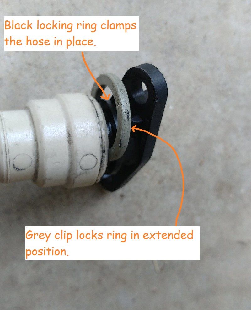
- the light gray fitting (brake booster hose) is the push-to-connect fitting, and that's where all the magic happens. As you pointed out, there is an o-ring on the inside that seals around the vacuum fitting. There are also sprung metal or plastic fingers that retain the mating vacuum fitting in place. If the push-to-connect fitting is working properly, you push until the fitting stops (this action collapses the sprung fingers, and allows the inserted tube/hose to slip inside the o-ring). You then pull straight back to "lock" the sprung fingers in the extended position, keeping the tube/hose from sliding out when there is pressure.
- the dark gray part (clip) is inserted in the gap to ensure that the push-to-connect fitting does not accidentally get pushed downward, potentially releasing the tube/hose.
Hope this is helpful.
|
|
|
|
|
08-26-2019, 07:56 PM
|
#7
|
|
Motorist & Coffee Drinker
Join Date: Jul 2014
Location: Oklahoma
Posts: 3,955
|
Quote:
Originally Posted by dsjwilson

78F350, great pics, but the function of each part is a little off. I have used similar push-to-connect fittings for many years at work, this is what each part does-
- the black part (vacuum fitting to manifold) is simply an adapter. One side connects to the engine, the other side is sized to fit into the push-to-connect fitting.
- the light gray fitting (brake booster hose) is the push-to-connect fitting, and that's where all the magic happens. As you pointed out, there is an o-ring on the inside that seals around the vacuum fitting. There are also sprung metal or plastic fingers that retain the mating vacuum fitting in place. If the push-to-connect fitting is working properly, you push until the fitting stops (this action collapses the sprung fingers, and allows the inserted tube/hose to slip inside the o-ring). You then pull straight back to "lock" the sprung fingers in the extended position, keeping the tube/hose from sliding out when there is pressure.
- the dark gray part (clip) is inserted in the gap to ensure that the push-to-connect fitting does not accidentally get pushed downward, potentially releasing the tube/hose.
Hope this is helpful.
|
Mr. Wilson, I think that your confusion about my confusion is mostly about the thing that you refer to as " sprung metal or plastic fingers that retain the mating vacuum fitting in place". I refer to that as the " black locking ring" that clamps the hose in place and " sliding ring" with my labels. Hopefully your description will clarify things for anyone who is confused by my labels.
The way I understand your understanding of the parts and their functions is very much the way I understand the parts and the way they function. Except the "light grey fitting (brake booster hose)" is actually white and dirty from years in an engine compartment. It may look grey, but without the dirt, I assure you, that part is white. The " sprung metal or plastic fingers that retain the mating vacuum fitting in place" is black plastic. It is an integral part of the " light gray fitting (brake booster hose)" [which is, as I just stated, white], making the part 996.110.170.00 (with option M249) or 986.355.575.06 a black piece of tubing with a white fitting on the end which is secured to it's attachment by a black plastic part with encircling "fingers" that lock in the extended position and an internal o-ring, pictured. Additionally there is; a grey piece that is actually grey (to my eyes a light grey rather than dark), that [in many more words that I used] " is inserted in the gap to ensure that the push-to-connect fitting does not accidentally get pushed downward, potentially releasing the tube/hose." and a black part which serves as a fitting on the right rear intake runner with option 249 (Tiptronic transmission) or left front intake runner (manual transmission). I shall not be appending this into my pictures as labels, but as an addendum I hope that it is enlightening to anyone who was confounded by my simplistic pictures.
Also, in case anyone is confused by your statement about "magic" happening, let me state clearly, There is No Magic used in the manufacture of these cars. It's all a balance of engineering and accounting, weighted towards the accounting.
...seriously though, I think we agree about function and you describe it well.
__________________
I am not an attorney, mechanic, or member of the clergy. Following any advice given in my posts is done at your own peril.
|
|
|
|
|
11-06-2025, 07:53 AM
|
#8
|
|
Registered Member
Join Date: Oct 2022
Location: NJ
Posts: 221
|
Hating to be the guy who resurrects an old thread for his own purposes, but I'm hoping that one of y'all can clue me in on where to look for this connection.
Either it came adrift or the vacuum line cracked on my way to work this morning, as I now have a massive vacuum leak in the rear and no power brakes.
I'm hoping that I can press the Easy Button in the parking lot this afternoon (not bloody likely, but a guy can dream).
Thanks in advance!
__________________
Tom Coradeschi
03 Boxster
|
|
|
|
|
11-07-2025, 03:03 AM
|
#9
|
|
Registered Member
Join Date: Oct 2022
Location: NJ
Posts: 221
|
So, once you take off the engine cover, the location is blindingly obvious! And, it’s where the break is.
FYI, front of the intake manifold, just to the left of the power steering pump.
__________________
Tom Coradeschi
03 Boxster
|
|
|
|
|
11-11-2025, 02:36 PM
|
#10
|
|
Registered Member
Join Date: Oct 2022
Location: NJ
Posts: 221
|
Following up to myself here.
If you need to do this job, removing the LR wheel and the plastic fender liner will help.
Two people will be required, and threading the new line in from the top appears to be the correct solution (we tried feeding it in from below, to no avail).
__________________
Tom Coradeschi
03 Boxster
|
|
|
|
 Posting Rules
|
You may not post new threads
You may not post replies
You may not post attachments
You may not edit your posts
HTML code is On
|
|
|
All times are GMT -8. The time now is 12:09 AM.
| |


 Parts Car, car parts
 Honda Del Sol(s)
 "Hers"
 My Original '99
 The 78 F350
 This
This That
That The S 2.5
 Other
Other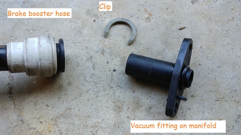


 Linear Mode


