Hope this helps visualize...
Quote:
Originally Posted by 78F350

In regard to the vacuum connections, here's that diagram, created with actual parts from a scrapped 2001 2.7L.
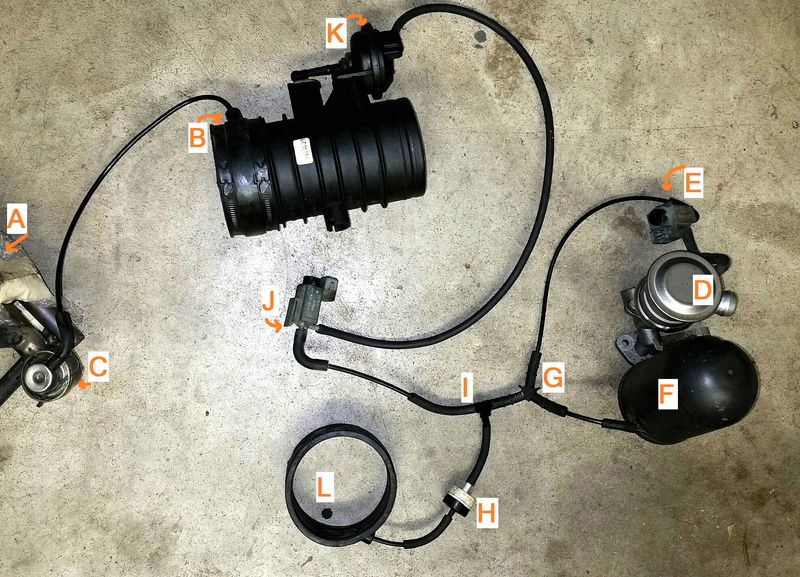
Notes:
-This picture shows what connections have to be made, the actual order of connections to the Y fittings (I) and (G) are not critical.
-The Tiptronic cars will have a 4-way connection at (I) or (G) with a line running to a changeover valve on the transmission.
It looks like a mess of tubes and parts, but in function it is fairly simple.
This shows 3 vacuum powered components: SAI, Resonance Flapper, and Fuel Pressure Regulator. Brake booster vacuum system is not shown.
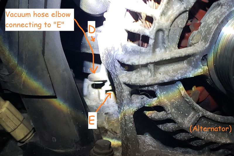
SAI: Vacuum source -> electric change-over valve (E) -> change-over valve (D).
Resonance Flapper: Vacuum source -> electric change-over valve (J) -> vacuum unit (K).
Fuel Pressure Regulator: Vacuum source (B) -> Pressure regulator (C) -> injector valves (A).
Rubber sleeves (L) and (B) are the source of vacuum from the intake. (H) is a check valve. (F) is the vacuum reservoir. |
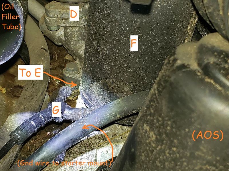
From the right rear of the engine looking forward under the intake:
Looking down to the right side of the engine with the front cross-tube removed:
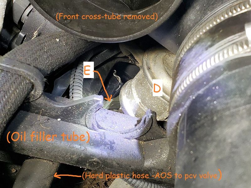
From the front of the engine looking back under the intake:
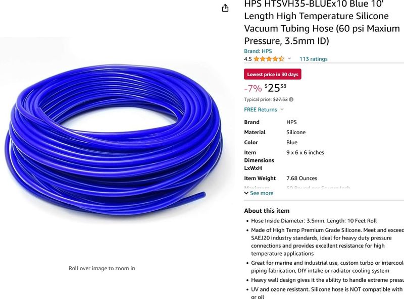
I buy this with a 3.5 or 3 mm ID and use it on a wide variety of cars with fittings from a local auto parts store to connect them or cut scraps from old tubing to connect.