Just a few visuals on the assembly balancing and a video showing my highly guarded & secret Newton's Cradle below. Run the vid half way to see the motion of the center cap. Just quick visuals for you guys, sorry, not the full thing (man, this is all time consuming this pic/vid/encoding thing loll).
Simple you may think but incurably powerful. Pure physics; 60+ years old solvers (NASA(nastran), Recurdyn, Adams, etc). Its all about the quality of the solvers really.
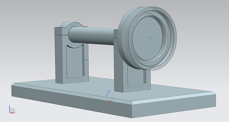
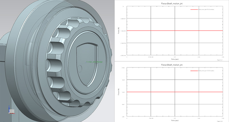
^ Here you can see the assembly I use for balancing rotary parts. It’s a base having a shaft rotating in the X axis. Not specific to the center cap I am doing now, I’ve actually used this for quite a few other parts successfully (custom spacers, CNC tool holders, custom rotary chucks soft jaws, center caps, etc etc).
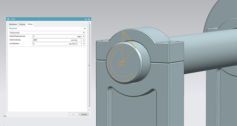
^ The shaft uses a driver (motor) set at 2,400RPM for this test. You can however set this to pretty much anything between 0 ~ 999,999,999rev/sec. Here we are testing vibration on a Porsche wheel with a diameter of 660MM (26"), or a circumference of 2073mm (660*PI). In velocity, and if spun at 2,400RPM, this gives us 82,938mm/sec (or 298km/h). So the target here is to rate the Great Center Cap for speed of 300Km/h without any sort of vibration.
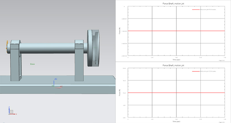
^ First thing first, calibrating the shaft coupled with the Porsche wheel hub (translucent part; right end side). We should be getting a flat line e.g. no changes in force magnitude anywhere = zero vibration.

^ With all the parts of the assembly inserted into the wheel hub, we are getting a vibration in the Z axis (i.e. up/down). So by deactivating each part of the assembly, it is easy to figure out which part is causing the wiggle. In the case of this assembly, the Center holding the P badge is the culprit.
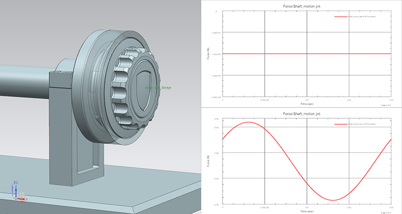
^ To make things a bit easier visually, we slow down the motion solver to 1 (one) rotation only so we can clearly see the vibration curve. Still rotating @2,400RPM (40rev/sec) however the time steps drops from 1 sec down to 0.025sec (e.g 1sec / 40rev per sec). So 1 full revolution only here. Easier to see than the above graph!
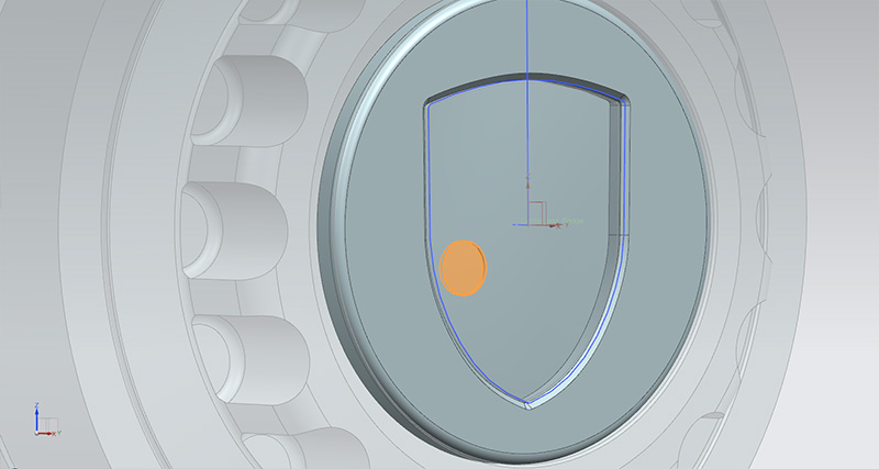
^ Now having found the culprit, you need to go back to the drawing board and counter-weight the part. In this case material had to be removed (orange). Once the center of mass gets back to zero, you re-import the part and re-solve the motion.
And BINGO!
^ As you can see, we are now getting 100% flat line per revolution (still at 2,400RPM). The badge is set to 50% transparent so you can see where the little pocket is located.
At the manufacturing stage, a very small pocket will need to be machined inside the area where the P badge goes and all will go back in perfect balance!
And that is how we design rotating parts and balance them using Multiphysics Motion Simulation ladies and gent. Fairly elementary and simple lollll
VIDEO
You'll see my Newton's Cradle in there (not a toy!). Again; incredibly powerful. CAE allows us to export Flexible Bodies (e.g. response dynamics) and import those inside Motion Sim. That is how we get table field of data for various materials used for creating parts (forces, damping, etc). This data is then used down the line for crash/impact analysis, fatigue analysis, stuff like that. Could be wrong but I think every engineers have a Newton's Cradle modeled (can't be found anywhere, you got to make your own and mine's not for sale loll)