Quote:
Originally Posted by KRAM36

|
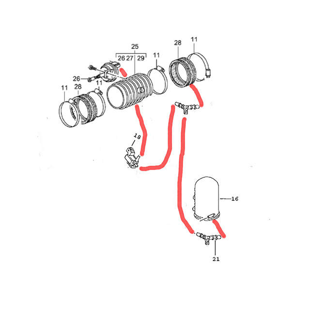
that is the diagram I see everywhere, however mine is different.
the first Y connector connect to the vacuum reserve canister, then to a second Y connector. the second one connects to the change over valve (I think) and to the boot on the resonance tube. another line runs from the change over valve to a vacuum solenoid on the resonance tube.
the 3rd connection on the 1st Y is the one that is not connected to anything and I cannot tell where it should go. I have spent hours searching online and looking at the engine trying to see if there is any other connection with a hose.
I would think that this was just a previous owner or mechanics "fix" for a broken line or something. but I have run across one other post where a guy had a similar setup. the post was from 2009 and I tried to reach out to him but I don't think he is still active.