After posting up yesterday I really thought I was going out to the garage to look at some camshafts. I should have known better though, since I've read about the use of some of the special Porsche tools required to properly remove the camshaft cover and remove the cam shafts.
Put simply, if you just remove the camshaft cover the cams will want to fall out and surely they'll get all gouged up in the process. So, tool # 9634 to the rescue.
Now I noticed on 986fix.com and also "project nutrod" that the guys who were kind enough to post up their pictures made their own special tools. So it seemed fitting that I would do the same. Time to go ponder the requirements.
Tool 9634 uses the same lug used to hold the LN engineering cam locking tool, only instead of engaging the key way there are two cylindrical features which lock in the centers of the cam shafts. Time to measure the distance between cam shafts. Now I noticed that on the two web pages referenced that they show the steps they used to create their tooling but don't mention the dimensions. It can't possibly be proprietary since anyone could measure the distance on their own.
Now maybe it's not kosher to publish the dimension so I won't, but it rhymes with 112.5mm. As for the diameter of the cylindrical features, you just need to dig out the socket head cap screws that used to hold your clutch pressure plate to your flywheel. They fit perfectly in the ends of the cams.
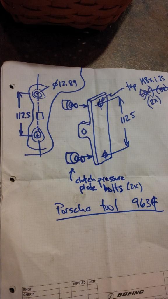
Going with that I imagined some tool made from a simple piece of angle. Two tapped holes 112.5mm apart and the clutch bolts threaded in. Then it would need a hole on the other leg of the angle, centered. The biggest hurdle would be getting a face of my new tool to line up exactly with the centerline of the two cam bolts.
I made a shopping trip with my sketch to the local home box store. I came up with a piece of L angle aluminum and after that I needed a spacer. The cheapest spacer I could come up with was a nut that was a slip fit for the M8x1.25 bolt (aka clutch pressure plate bolt) that would hold the tool to the head.
Next it was off to my son's house to commandeer the drill press I left with him. Getting the two cam bolts to line up on the same center as the inside face of my new "spacer" would be easier done than said. Behold:
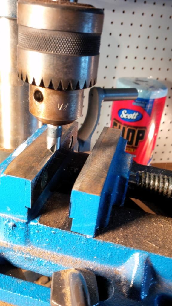
I needed a rigid way of starting the two threaded holes if I had any chance of nailing my 112.5mm goal. I chucked up a stiff drill bit which I'm going to erroneously refer to as a center drill (it's a countersink tool in real life, but the closest they had at Lowe's). Bottom line, it wasn't going to wander when starting a hole.
Chucking it up in the drill press I brought it down and rotated my table until the rear (non moving jaw) of my vise was right on the money for the tip of the "center" drill. Then I put my angle in, with the spacer (aka M10 nut) faced towards the back jaw. I could then start a hole any damn where I pleased, and then slide the work piece along the vice jaw exactly 112.5mm.
I did that by bringing my center drill down and just marking off the drill point for the future hole. Then I scribed an arc at 112.5mm. All I would have to do is loosen the vise and slide the part down until the tip of the center drill intersected with my arc.
I'm skipping a couple of steps here but this is another look
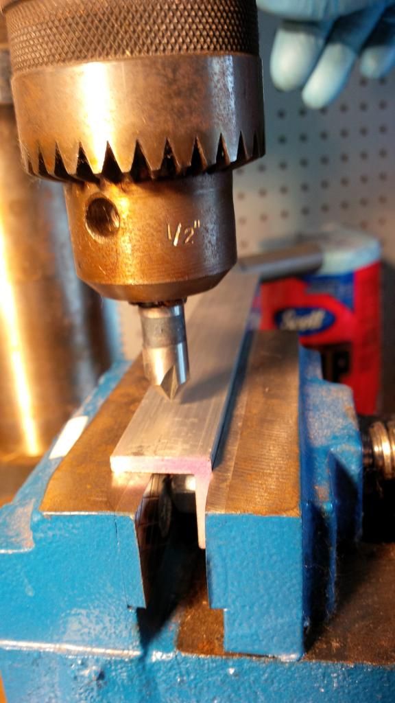
As you can see, the face of my spacer being pushed up against the rear jaw of the vise assures the holes will be exactly lined up with the lug on the cylinder head.