Over the course of the last two weekends I installed the Direct Oil Feed system and I thought I would show some pictures about how it's done and a few tips that the instructions didn't cover.
Removing the transaxle, clutch, and flywheel have been documented, so I won't cover that here. I will say that it is well worth the time to remove the rear bumper cover and aluminium bumper bar, as well as the secondary cats. It makes life so much easier when working under the car on jack stands.
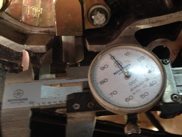
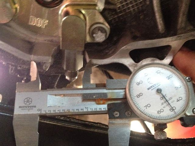
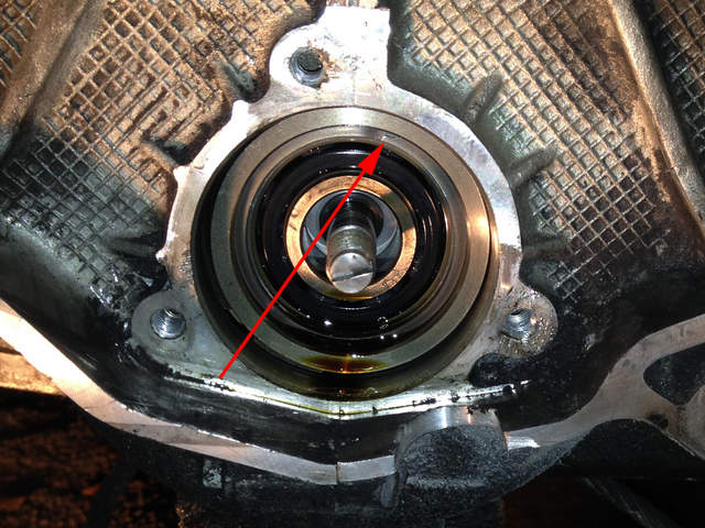
Before removing the IMS bearing flange, you want to mark out and cut the lip of the engine case to accommodate the oil line fitting. The instructions say to to make two lines from the mold mark on the engine case, 13mm and 33mm away. Those distances didn't work for me. More suitable numbers (in my case, anyway) turned out to be .6" and 1.45" (about 15mm and 37mm). The instructions also say "You can cut all the way through the bell housing nerve up to but not into the engine case." I don't know exactly what that means, but you should cut up until you are flush with this surface:
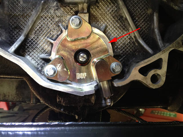
These pictures are after the new flange had been installed:
The instructions tell you to first remove the existing IMS bearing flange and then remove the rear IMS to cam tensioner. I feel that this is wrong and will only lead to a more difficult time removing the flange because of the added side load. I emailed the manufacturer, but never got a response.
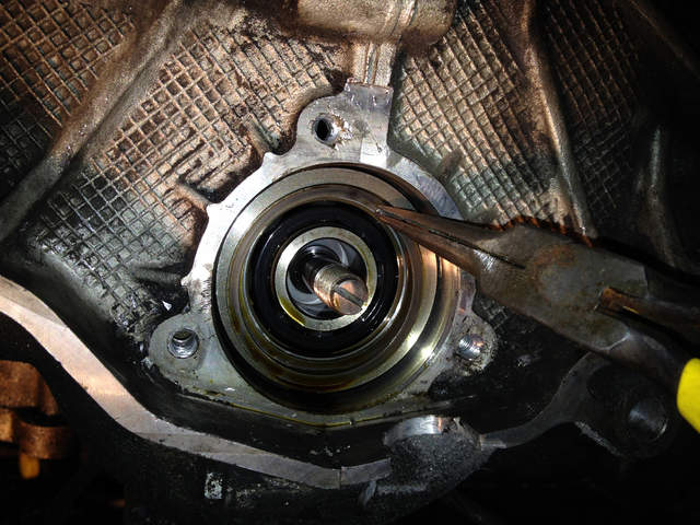
Here the previous IMS flange has been removed. In all of the directions I have read, it states that the spiral clip retainer will collapse inward when you pull on the bearing with the removal tool. I found that I could simply grab the end of the clip with needle nose pliers and "unspiral" it.
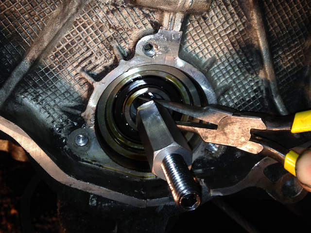
Next you have to thread the hex shaft onto the bearing stud. I found that the needle nose pliers also worked for keeping the stud from rotation while screwing the shaft on.
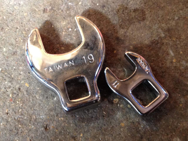
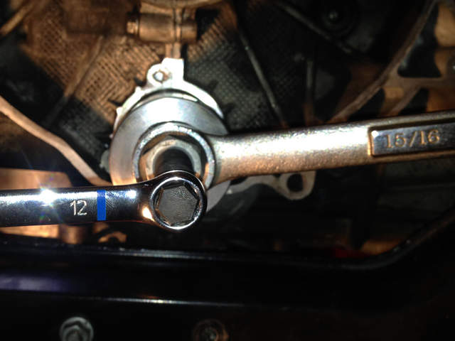
Here are the wrench sizes. The larger diameter is supposed to be 24mm, but I don't have one. A 15/16" 6-point wrench works just fine (and also works for rotating the engine from the pulley side when aligning TDC).
The instructions also make no mention of putting the bearing and install tool in the freezer before installation, but I did. Next install the bearing and flange according to the instructions.
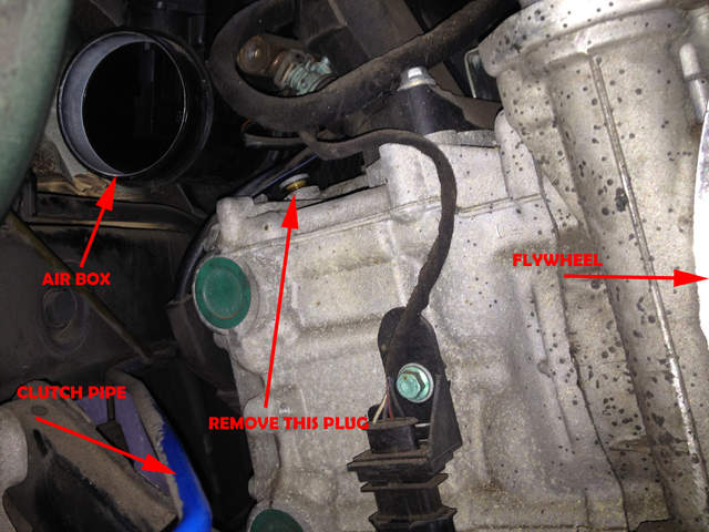
Now you have to open up a plug where the new oil feed will be coming from. It took my probably 5 minutes of searching to find the plug they were referring to, and it's not the easiest to get at because the air box and fuel rail are partly in the way. Not to mention your car is probably up on jack stands, so you need a ladder or something to stand on in order to see and reach the plug. The instructions show an allen wrench going into the plug for removal. This was NOT the case for my engine (2000 3.2). It turns out to be a T40 Torx.
I discovered this once I had already stripped the end of it out with an allen wrench. I ended up removing it with a pair of robo-grips, but pliers or channel locks, or vice grips would have worked as well. They are aluminium and not torqued down very hard, so it didn't take much robo-gripping.
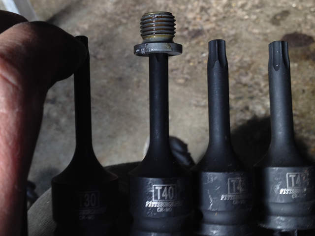
Here is the plug, as seen from underneath the car, facing the flywheel:
Installation of the new aluminium adapter and oil hose require two crowfoot wrenches, 19mm for the adapter and 11mm for the nut at the end of the hose: