 04-06-2014, 06:05 AM
|
#1
|
|
Registered User
Join Date: May 2012
Location: Kalamazoo, MI
Posts: 149
|
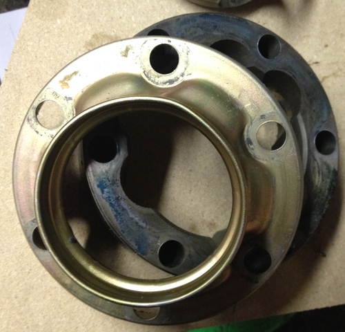
Inner CV Joint Assembly Instructions
I have disassembled and cleaned my inner CV's in my parts cleaner, but in doing so I have noticed that there is a groove on the inner splines. I recall reading a post on one of the forums where someone asked what direction the groove points and it was answered, but for the life of me I can't find the post. Anyone have the instructions?
Also, is there a difference between left and right? I didn't think to mark them. Is the zinc plated boot attachment ring supposed to be easily removable from the outer race? I tapped on one a bit with a hammer and punch and it didn't move anywhere, so I didn't want to force it. I wouldn't mind getting them apart to clean between the two.
Benjamin
__________________
2000 986 S - "The Black Widow"
|

|

|
|
04-06-2014, 06:43 AM
|
#2
|
|
Registered User
Join Date: May 2012
Location: Kalamazoo, MI
Posts: 149
|
I've made a little more progress and was able to get the boot rings off the outer races with a hammer and flat punch. Perhaps soaking overnight in cleaner helped to free them up.
It also appears that the cages are directional as there is more of a chamfer on one side than the other.
__________________
2000 986 S - "The Black Widow"
|
|
|
|
|
04-06-2014, 08:16 AM
|
#4
|
|
Registered User
Join Date: May 2012
Location: Kalamazoo, MI
Posts: 149
|
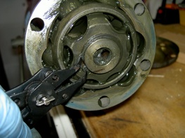
Thanks Eric, To clarify, the hammer and flat punch was to separate these two parts. It would be called more of a "tapping" than a "hammering". I tapped along the outer edge in a circle a few times and it came off. Also, as you can see there is a blue/green substance on the mating surface that I think may have been sticking the two parts together. I don't know if it is supposed to be there or just something done in a previous repair.
I checked out your links, but they don't provide the info I'm looking for.
__________________
2000 986 S - "The Black Widow"
|
|
|
|
|
04-06-2014, 08:25 AM
|
#5
|
|
Registered User
Join Date: May 2012
Location: Kalamazoo, MI
Posts: 149
|
Quote:
Originally Posted by Benjamin

I checked out your links, but they don't provide the info I'm looking for.
|
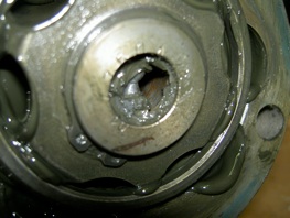
I take that back. I think these two photos tell me everything I need to know. The grooved side of the inner race goes towards the axle and the bigger chamfer goes towards the dust cap. At least I think that's what I'm seeing:
__________________
2000 986 S - "The Black Widow"
|
|
|
|
|
04-06-2014, 04:25 PM
|
#6
|
|
Registered User
Join Date: May 2012
Location: Kalamazoo, MI
Posts: 149
|
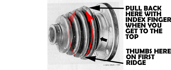
The inner CV joints are back together with new boots and clamps. Getting the wide end of the boots on is somewhat of a challenge, but by the 4th one I think I figured out a technique. For the outers, the key was to have the axle straight out from the CV. I rested it on my shoulder while pushing on the boot. To get the end to go on I got the bottom side on first and then, with both thumbs behind the first ridge, with firm pressure I slid my thumbs around to meet at the top. If the top doesn't want to come out to go on the outside of the flange and keeps getting caught on the inside edge, you can squeeze and pull back a bit on the 2nd ridge to make the lip flex outward. The inners are a little easier (if the trans is removed and you're sitting under the car) because you can see and reach things a little easier.
As far as CV assembly, I have seen other threads that people say they reassembled everything and the joint wouldn't flex. The first time I tried, that's what happened. The inner and outer races have angled bearing surfaces where the balls ride. Since they are angled, there are skinny and wide spots on the face of each race. If you line up the skinny spots on inner and outer race, it will go together, but no flex. Line up the skinny on one with the wide on the other, and it all works. I wish I would have taken pictures.
__________________
2000 986 S - "The Black Widow"
|
|
|
|
|
04-07-2014, 05:03 AM
|
#7
|
|
Registered User
Join Date: Dec 2007
Location: Seattle
Posts: 735
|
[QUOTE=Benjamin;394486] as you can see there is a blue/green substance on the mating surface that I think may have been sticking the two parts together. I don't know if it is supposed to be there or just something done in a previous repair./QUOTE]
It may be loctite applied too generously on the bolts and it seeped into the area between the flanges.
__________________
2000S Ocean Blue Metallic- 116K
3X Water Pump, Clear side markers, Crios Mod, Front engine mount, Flywheel, clutch, RMS, AOS, MAF, serpentine belt, power brake vacuum line, battery, 2X CV boots, Fuel filter, Oil filler tube, 3X ignition switch, 90K service, gas cap, Coolant tank
|
|
|
|
|
04-07-2014, 05:52 AM
|
#8
|
|
Theoretical propagandist
Join Date: Dec 2011
Location: Pacific Northwest
Posts: 793
|
Congratulations on getting this done! I always love hearing about how folks worked through a tough issue and figured it out. Cars really are a work in progress.
__________________
When life throws you curves, aim for the apex...
|
|
|
|
|
04-07-2014, 07:03 AM
|
#9
|
|
Registered User
Join Date: May 2012
Location: Kalamazoo, MI
Posts: 149
|
Quote:
Originally Posted by Spinnaker
It may be loctite applied too generously on the bolts and it seeped into the area between the flanges.
|
I don't believe those bolts are supposed to have loctite on them. That's not to say someone didn't use it somewhere along the way, but I see the same residue on this picture from Pedro's tutorial:

Quote:
Originally Posted by Eric G
Congratulations on getting this done! I always love hearing about how folks worked through a tough issue and figured it out. Cars really are a work in progress.
|
Thanks Eric. I can't count the number of threads where someone has asked a question, received a couple different answers, and then they never follow up to report what actually worked or didn't work. I always try to complete mine, even if I ask a question that gets no response and I figure it out for myself. If someone ever searches for that topic, they get both the question and answer. There are times in non-Porsche forums where I asked and answered my own question, and then referred back to it several months or years later because I couldn't remember how I had done it.
I'm really pleased with how this whole group of projects is going (IMS bearing, DOF, axle boots, oil, trans oil, stereo upgrade). Pretty much everything has gone according to plan. Nothing broken when removing, nothing stuck, no stripped bolts. I have ended up spending the time to remove a few more components than probably absolutely necessary such as the rear bumper, air intake tube, side heat shields, cats, but they all came off without incident and have made life so much easier. Some of the parts have been delayed in shipment which at first was frustrating, but in retrospect I see that it has given me extra time to be very meticulous with everything and not cutting corners by being in a rush.
__________________
2000 986 S - "The Black Widow"
|
|
|
|
|
04-07-2014, 07:26 AM
|
#10
|
|
Registered User
Join Date: May 2012
Location: Kalamazoo, MI
Posts: 149
|
Here are some drawings to hopefully illustrate the CV assembly/boot installation techniques that I was talking about :

__________________
2000 986 S - "The Black Widow"
|
|
|
|
 Posting Rules
|
You may not post new threads
You may not post replies
You may not post attachments
You may not edit your posts
HTML code is On
|
|
|
All times are GMT -8. The time now is 06:45 AM.
| |


 The Black Widow
 Esmeralda
 Gadget
 Sasha
Sasha Gertrude
 Bernice
 Mrs. T
 Linear Mode


