 03-10-2015, 09:41 PM
|
#1
|
|
Registered User
Join Date: Oct 2014
Location: Patriot IN
Posts: 41
|
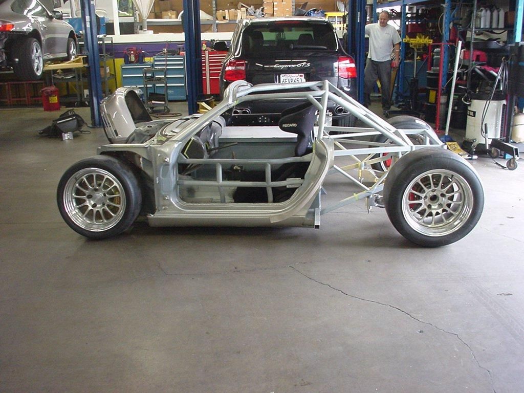
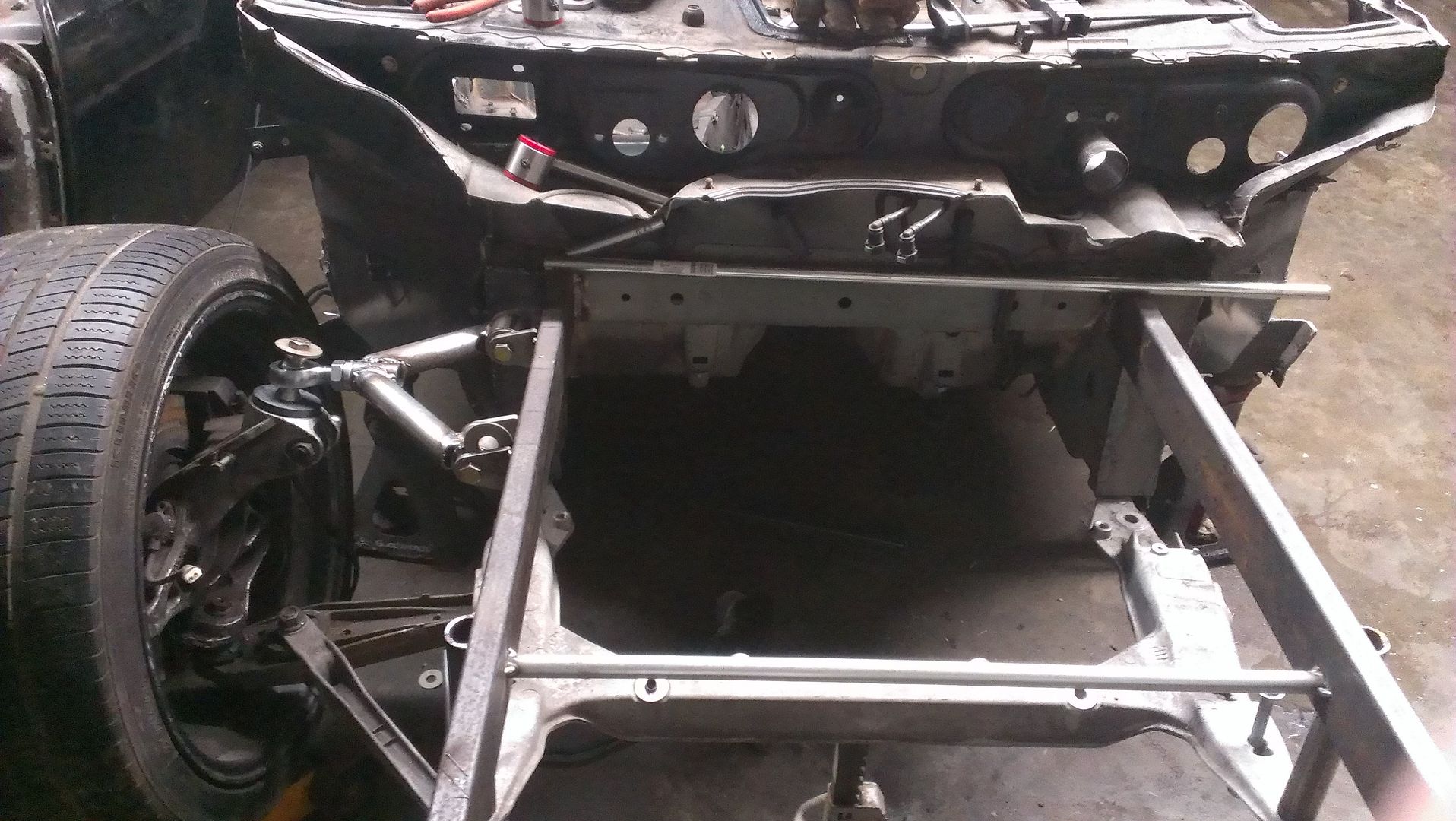
Boxster tube frame/ chassis ideas?
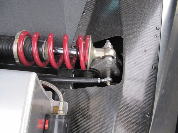
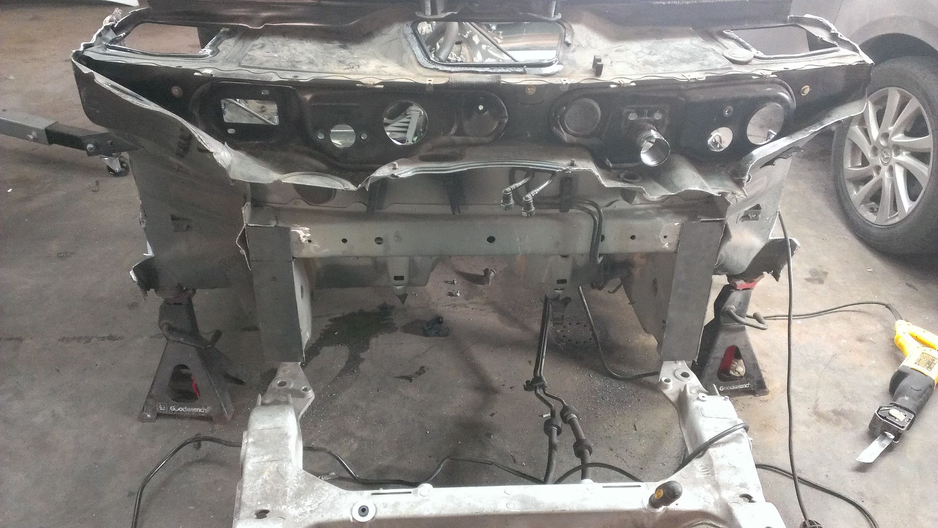
I looking for ideas on a tube frame front end. The crazier the better, Ideally I would like to convert to double wishbone front suspension. Also has anyone converted to tubular control arms?
Does anyone have anymore info on the first pic? I dont remember where I found it I would love some more pics of it.
|

|

|
|
03-11-2015, 03:45 AM
|
#3
|
|
Registered User
Join Date: Jun 2014
Location: LB, Germany
Posts: 1,526
|
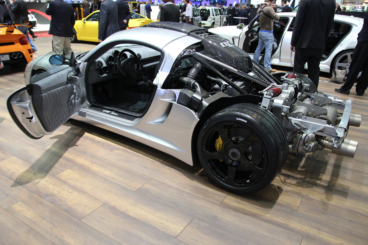
Don't have infos on you pic. But another car with that idea:
RUF CTR3
Uses a 987 front (so it's also crash proved), removes complete back. Adds a wireframe to the back. Longer wheelbase.


Last edited by Smallblock454; 03-11-2015 at 03:50 AM.
|
|
|
|
|
03-11-2015, 07:03 AM
|
#4
|
|
Registered User
Join Date: Jun 2014
Location: LB, Germany
Posts: 1,526
|
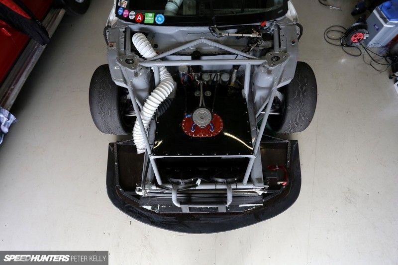
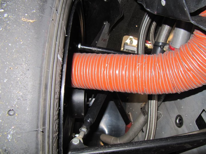
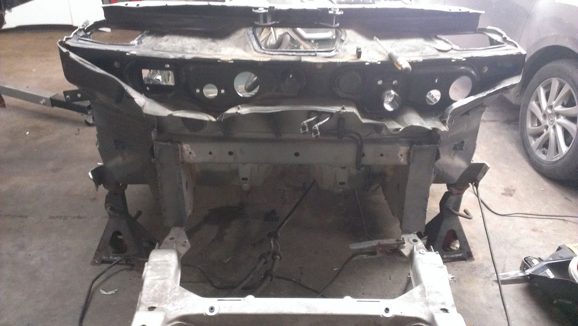
This is the car from your 2 picture. Dont't kniw if it is the same on the 1 picture - think not, because the cage is totally different.
The Twin Turbo V8 Porsche Boxster - Speedhunters

|
|
|
|
|
03-11-2015, 10:20 PM
|
#5
|
|
Registered User
Join Date: Oct 2014
Location: Patriot IN
Posts: 41
|
Last edited by jarrodblake; 03-11-2015 at 10:27 PM.
|
|
|
|
|
03-13-2015, 10:24 PM
|
#6
|
|
Registered User
Join Date: Oct 2014
Location: Patriot IN
Posts: 41
|
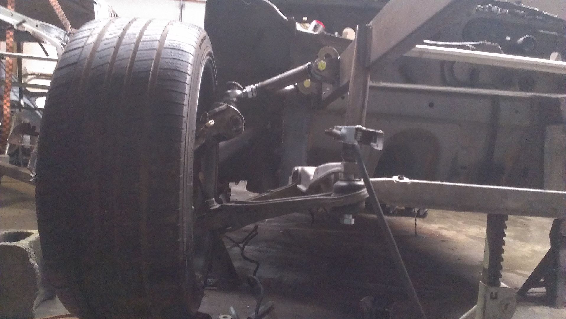
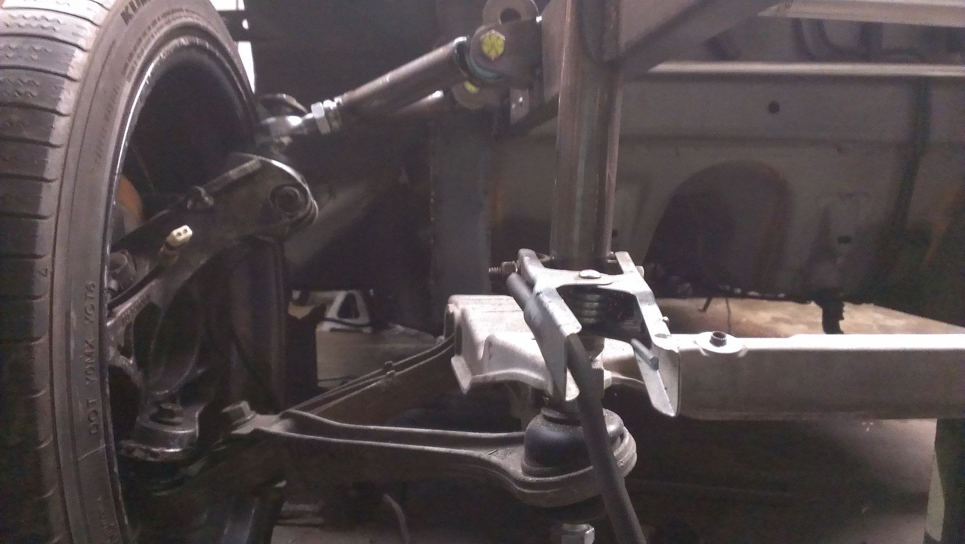
Talk to me about control arms and tubing sizing/ hard ware and mounting the upper control arm to the stock hub.
What I am thinking about using for the upper control arm any thoughts?
1-1/4 OD x .120 wall DOM
Weld In Tube Adapter 3/4-16 Thread .120 Heim Joint Tube End 1 1/4 O.D
rod ends/ heim joints, 3/4"-16 Shank/Hole
3/4" to 1/2" HIGH MISALIGNMENT SPACER HEIMS
I would like to reuse the stock hubs. However a problem with using the stock hubs is finding a way to mount the upper control arms. The stock hub uses a 2 inch strut.

I have a few ideas on mounting the upper control arms to the stock hub. But nothing that I really like yet. Anyone have any other ideas?
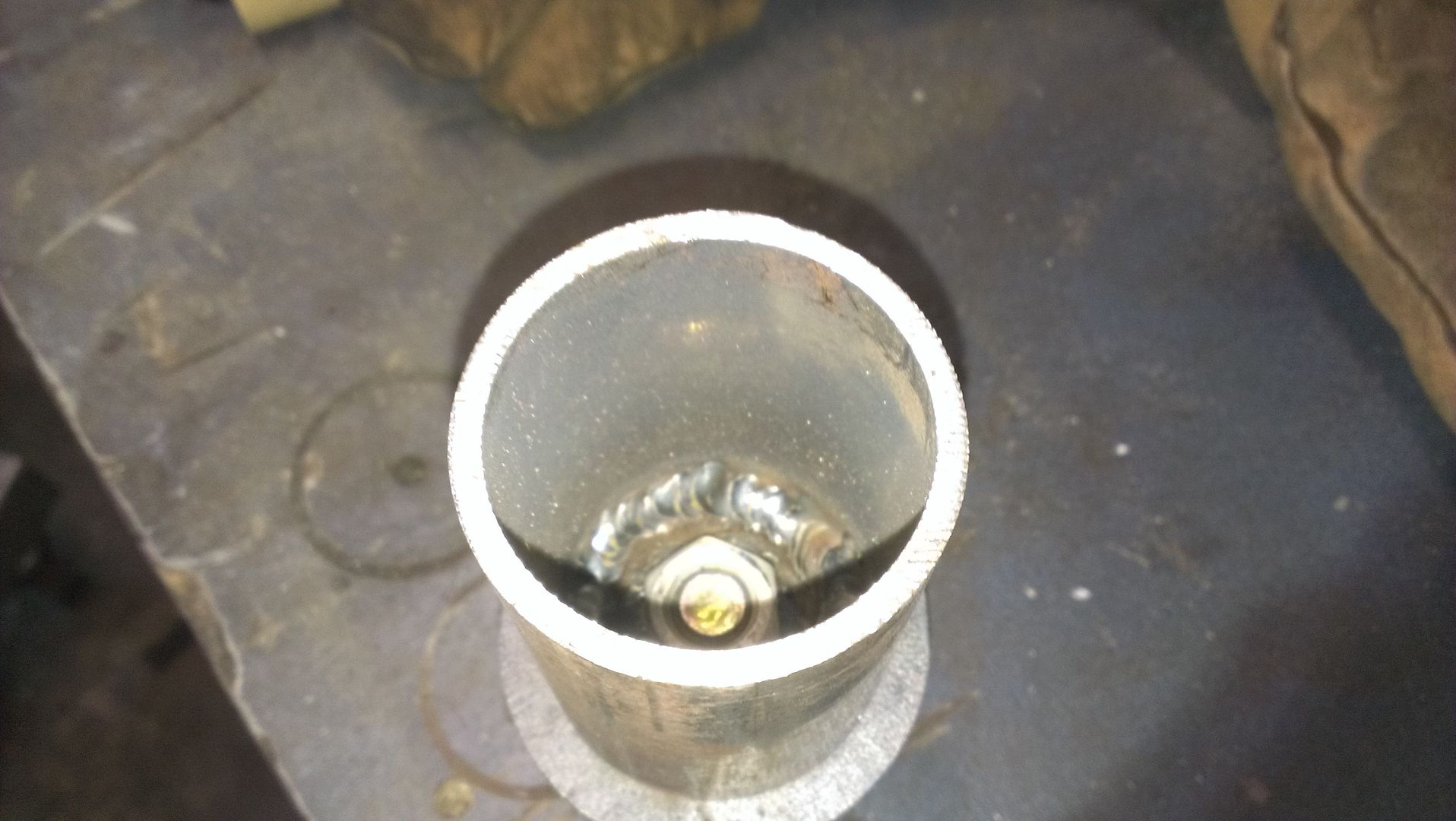
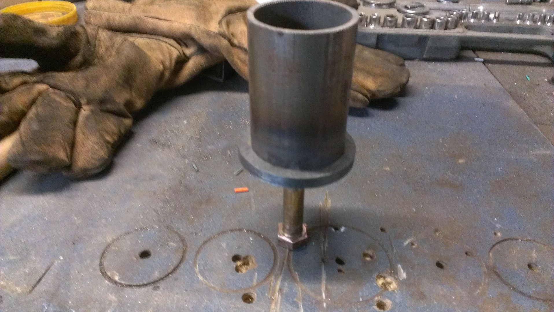
A) I take a piece of 2'' 120 wall DOM tubing and weld in a 3/8 plate with a 1/2 hole and mount the upper control arm using the him joint.
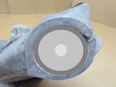
B) I take a piece of 2'' 120 wall DOM tubing and weld an reducer then weld in a Tube Adapter with a half inch tread. But it would make the hub taller 1-2 inches? then mount the upper control arm using the him joint.
C) I found a few pics of a offset adapter in a strut style hub that was converted to a pushrod suspension set up/ same idea as (A)


|
|
|
|
|
03-14-2015, 07:54 AM
|
#7
|
|
Registered User
Join Date: Apr 2010
Location: Canada
Posts: 3,153
|
could you not just take a solid piece of aluminum, machine to 2" OD and the length you need, then drill it through for a long heim joint (offset if required)?
|
|
|
|
|
03-14-2015, 08:59 AM
|
#8
|
|
Registered User
Join Date: Jun 2014
Location: LB, Germany
Posts: 1,526
|
How will you realize the linkage of the pushrod system?
Do you want to use a double withbone system with a pushrod?
I think that has to be designed/engineerd first. Than you can think about if and how to use the stock control arms.
There are completely different forces working.
Last edited by Smallblock454; 03-14-2015 at 09:01 AM.
|
|
|
|
|
03-15-2015, 11:53 PM
|
#9
|
|
Registered User
Join Date: Oct 2014
Location: Patriot IN
Posts: 41
|
I have thought about having one machined, but I don't really see any benefit in doing that other then looks?
As far as designing a push rod setup, I have a few ideas on placement and how i'm going to design it (no real measurements yet). But I think I would need to build the upper control arms first? and yes a double wishbone ( same thing as a double A Arm setup) system with a pushrod to coilover set up.
At the moment i'm looking at 13.84'' (Extended Length) and 10'' (Collapsed Length W/out Bumper) coilovers with 3.86 stroke
And the 12.84'' (Extended Length) and 9.50'' (Collapsed Length W/out Bumper) coilovers with 3.36 stroke.
As for the bell crank arms, I have not calculated the motion ratio vs. Suspension travel ratio yet as I cannot find the stock boxster Suspension travel ratio. That said I don't believe the upper control arms will have any effect on the pushrod set up other than placement, but I already have two ideas on that.
Also what do you mean by (There are completely different forces working.)?
That said I plan on ordering tubing soon. I have two sized in mind. The cost is almost the same. I'm just trying to get an idea on sizes. I feel that 1-1/4 is over kill and may be to big, However I don't know if .95 wall will be adequate.
What I am thinking about using for the upper control arms, any thoughts?
1-1/4 OD x .120 wall DOM
Weld In Tube Adapter 3/4-16 Thread .120 Heim Joint Tube End 1 1/4 O.D
rod ends/ heim joints, 3/4"-16 Shank/Hole Chromoly Rod End Static Load Capacity:29,127 lbs.
3/4" to 1/2" HIGH MISALIGNMENT SPACER HEIMS
or
1 .95 wall DOM
Weld In Tube Adapter 5/8-20 Thread .95 Heim Joint Tube End 1 O.D
rod ends/ heim joints, 5/8 Shank/Hole Chromoly Rod End Static Load Capacity:21,219 lbs.
5/8" to 1/2" HIGH MISALIGNMENT SPACER HEIMS
|
|
|
|
|
03-18-2015, 02:21 PM
|
#10
|
|
Registered User
Join Date: Oct 2014
Location: Patriot IN
Posts: 41
|
Well I ordered all the parts for my upper control arms, I went with.
1-1/4 OD x .120 wall DOM
Weld In Tube Adapter 3/4-16 Thread
3/4-16 Heat Treated CHROMOLY Heim rated at 34,000 load capacity

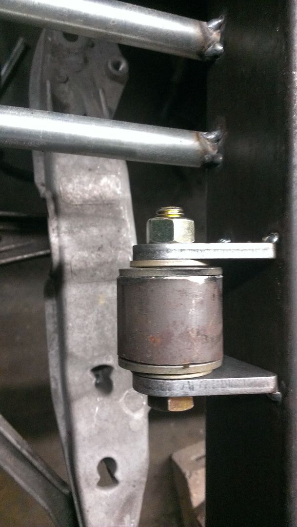
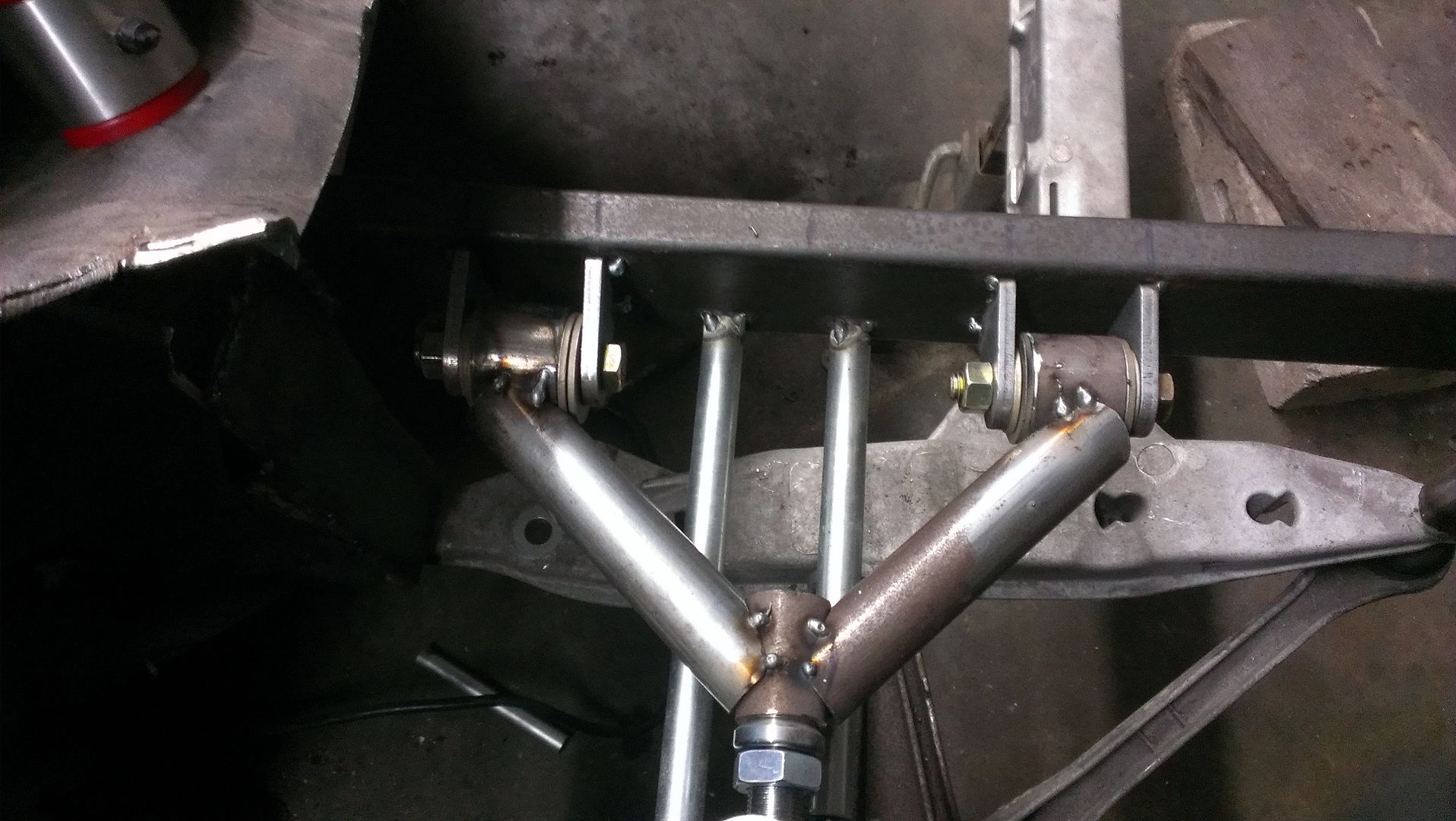
I was going to use hims on everything, however after a lot of reading I decided on using bushing on the control arm to frame joint.
Steinjager J0012587 Poly Bushing Weld On Kit 1/2 Bore 1.75 Wide

Also does anyone know of a good program to calculate the motion ratio vs. Suspension travel ratio? or a good 3d molding program that can?
The two coilovers i'm looking at using have a 3.36 stroke and a 3.86 stroke the stock boxster has a 6.47 stroke.
|
|
|
|
|
03-19-2015, 01:44 AM
|
#11
|
|
Registered User
Join Date: Jun 2014
Location: LB, Germany
Posts: 1,526
|
Hi,
different forces: what i've meant is that if you reduce the car wheight by using a wireframe as chassis, you'll need a different spring and damping rate. Maybe strength, or energy is a better term for force.
Additionally the pushrod system will need a linkage to the wheel carrier. The wheel carrier was designed to take the main forces at the top where it connects to the damper/spring. If you use a double wishbone system, this won't be the problem. The problem can be the connection for the pushrod linkage at the wheel carrier.
The pushrod system has also the advantage to remove weight from the wheels (unsprung mass). That also means that you need to adjust dampening rates. The disadvantage is a little bit more friction because of the redirecting points.
Maybe you can adjust things with the gear ratio of the pushrod system.
Hope that makes sense to you. I'm not very good in translating technical terms from german to english.
Last edited by Smallblock454; 03-19-2015 at 05:08 AM.
|
|
|
|
|
04-08-2015, 10:08 PM
|
#12
|
|
Registered User
Join Date: Oct 2014
Location: Patriot IN
Posts: 41
|
Quote:
Originally Posted by Smallblock454

Hi,
different forces: what i've meant is that if you reduce the car wheight by using a wireframe as chassis, you'll need a different spring and damping rate. Maybe strength, or energy is a better term for force.
Additionally the pushrod system will need a linkage to the wheel carrier. The wheel carrier was designed to take the main forces at the top where it connects to the damper/spring. If you use a double wishbone system, this won't be the problem. The problem can be the connection for the pushrod linkage at the wheel carrier.
The pushrod system has also the advantage to remove weight from the wheels (unsprung mass). That also means that you need to adjust dampening rates. The disadvantage is a little bit more friction because of the redirecting points.
Maybe you can adjust things with the gear ratio of the pushrod system.
Hope that makes sense to you. I'm not very good in translating technical terms from german to english.
|
I completely understand what your saying, As far as the coilovers I will be using, they will be custom ordered to the specifications that I need such as spring rates and damping rates. The dampeners with also be adjustable and can be sent back at anytime to be re valved if needed. That said I have no plan to order them any time soon. It wont be till the car is almost finished before I order them.
I have no problem making lower control arms as well if they are needed to support the additional load of the push rod setup. I also have another idea for the push rod setup that would allow me to keep the stock lower control arms.
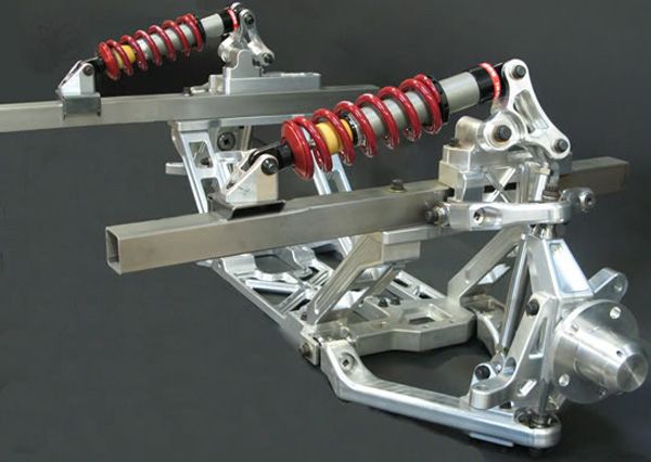
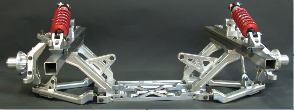
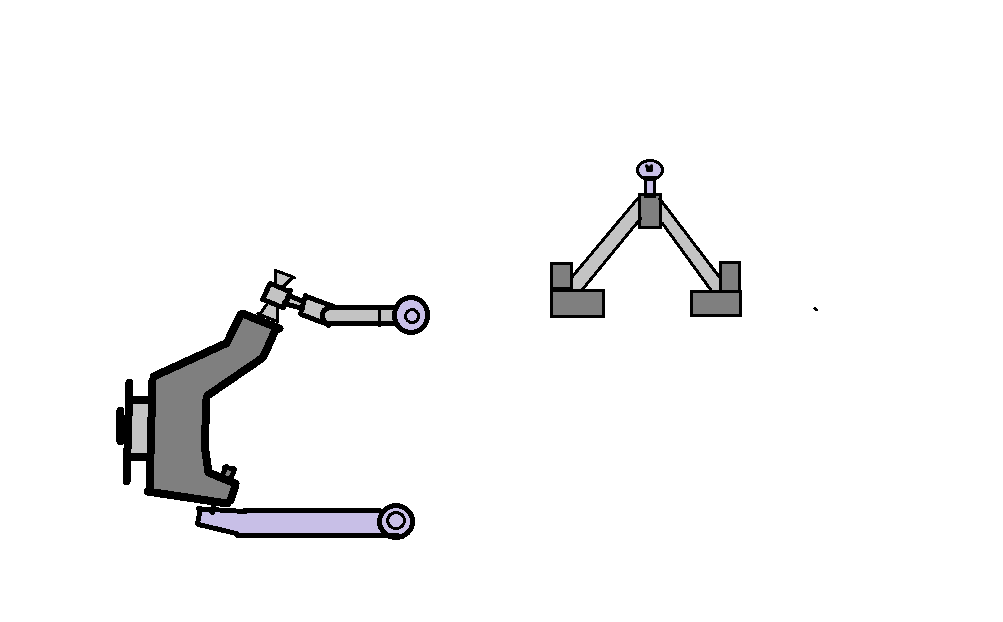
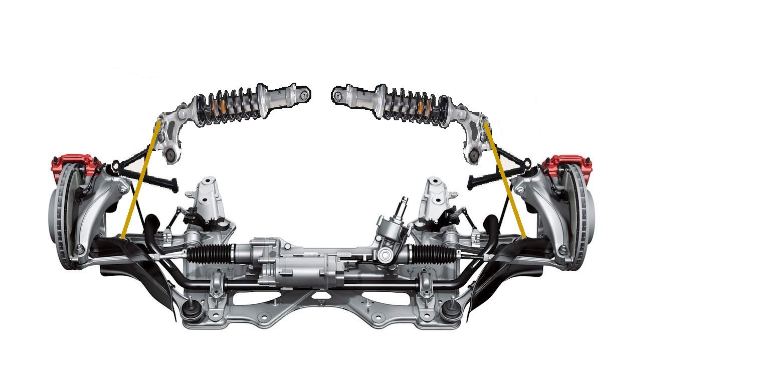
Here is a standard push rod setup
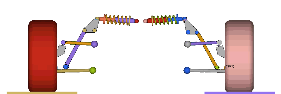
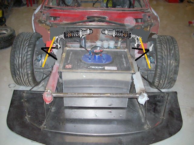
Here is an idea that would let me keep the stock lower control arms.
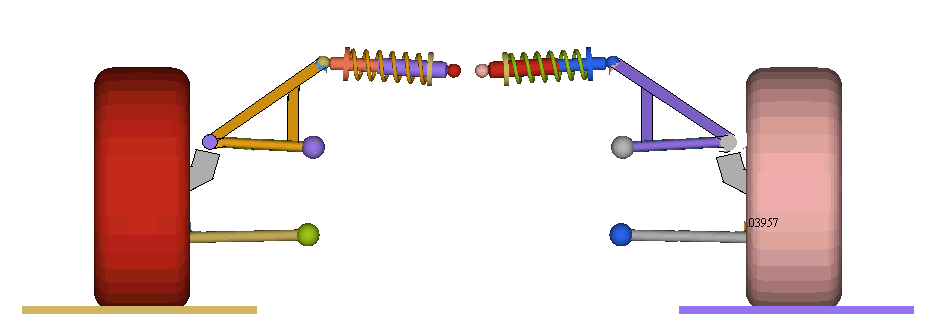
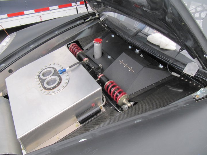
I'm also considering mounting the shock along the frame rails like this. It would save space and it should solve any interference issues I would come across.
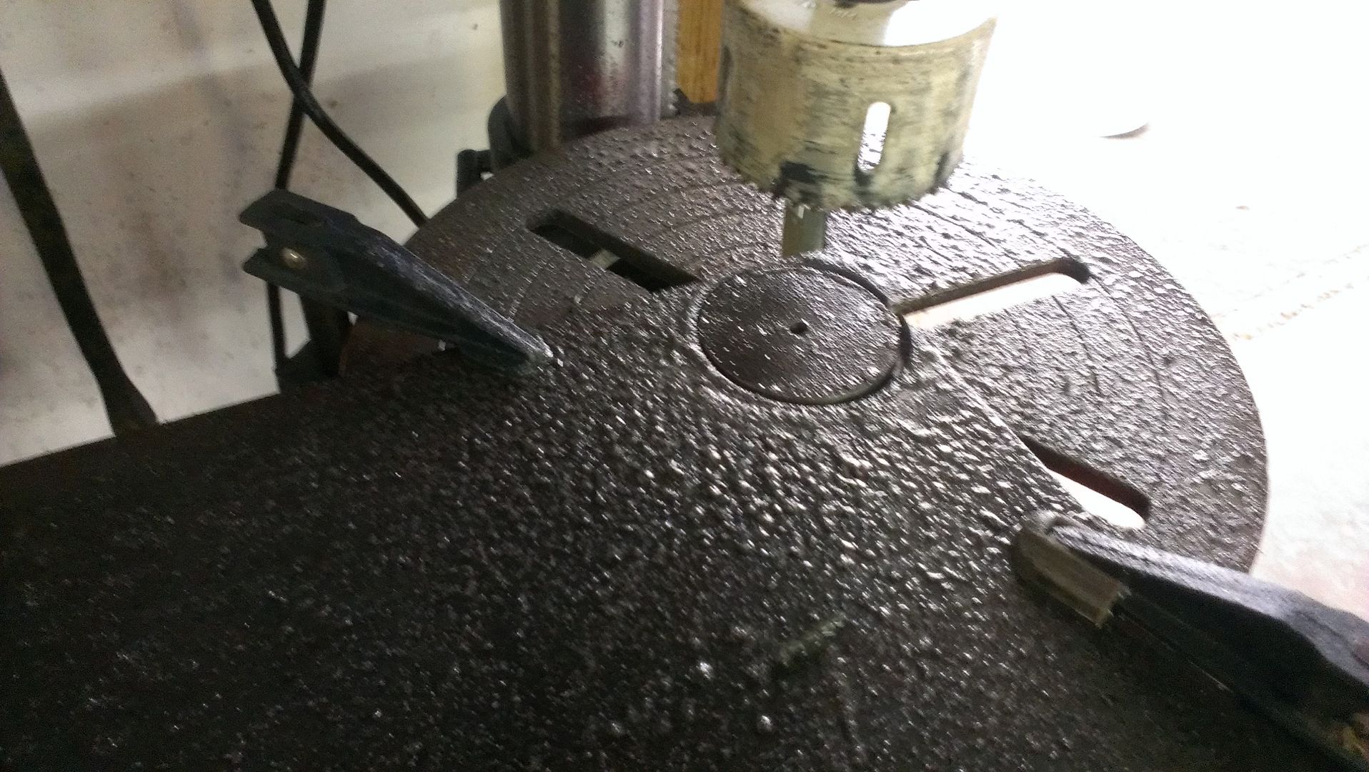
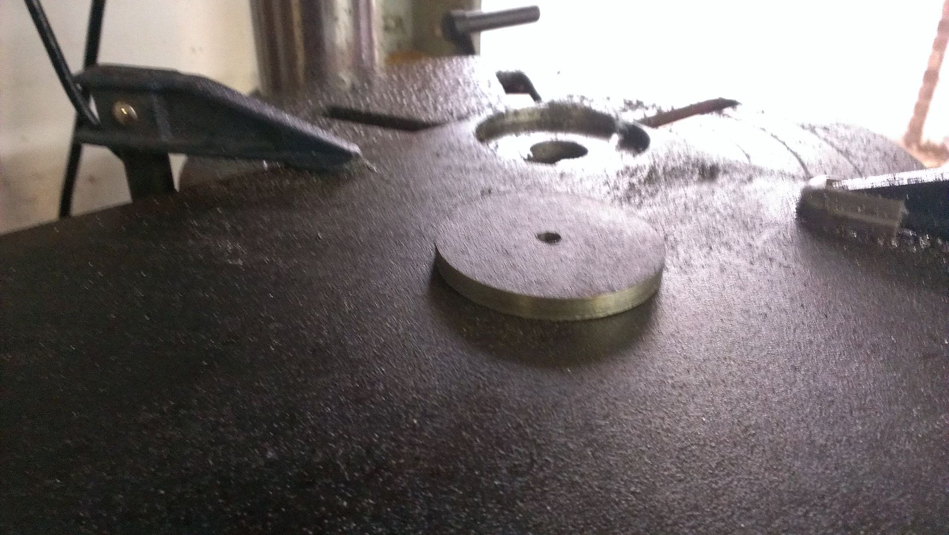
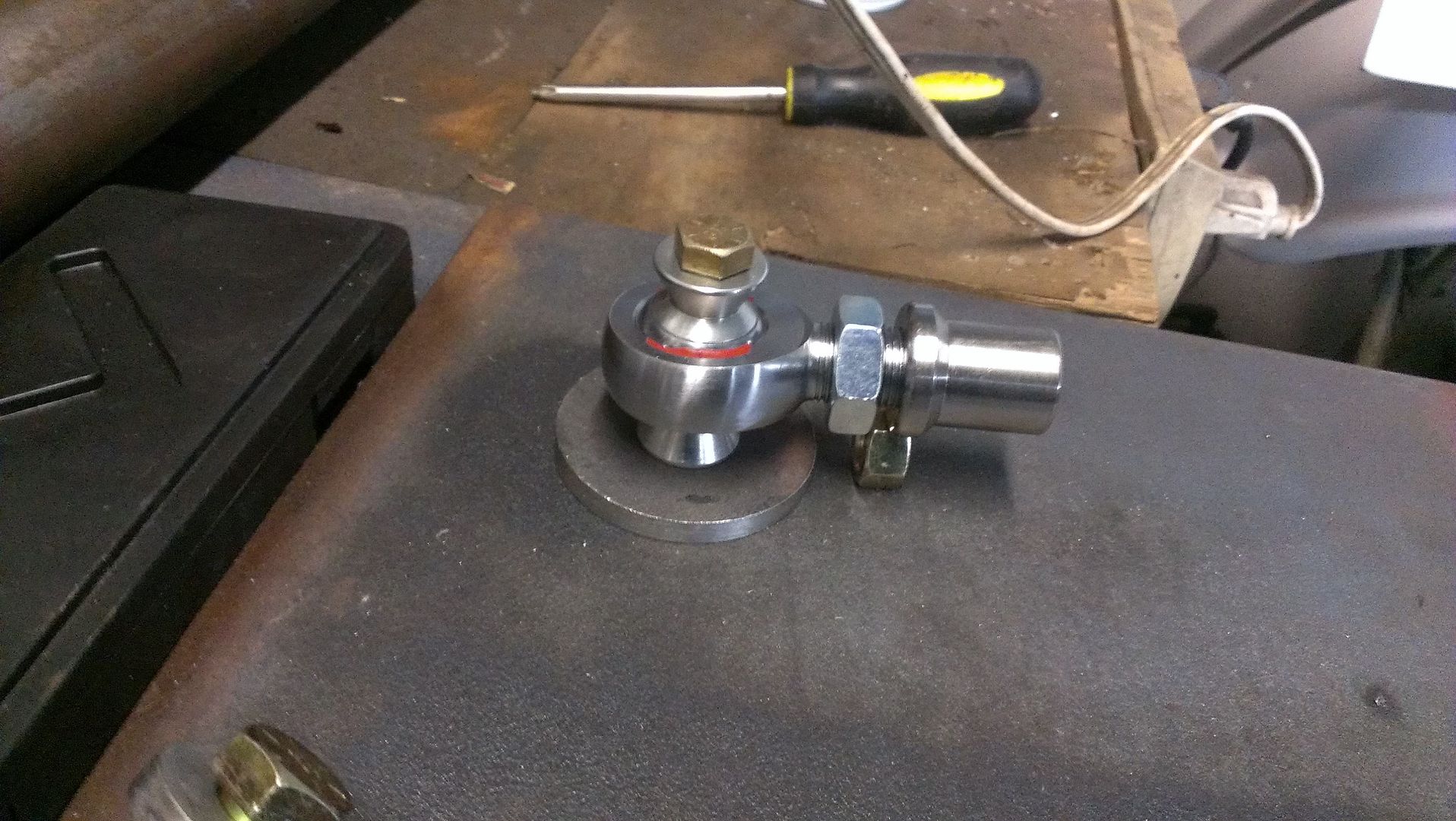
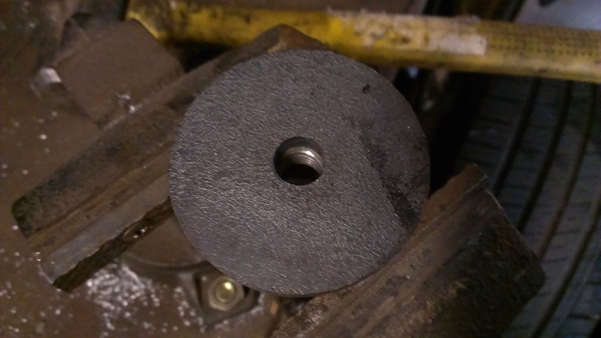
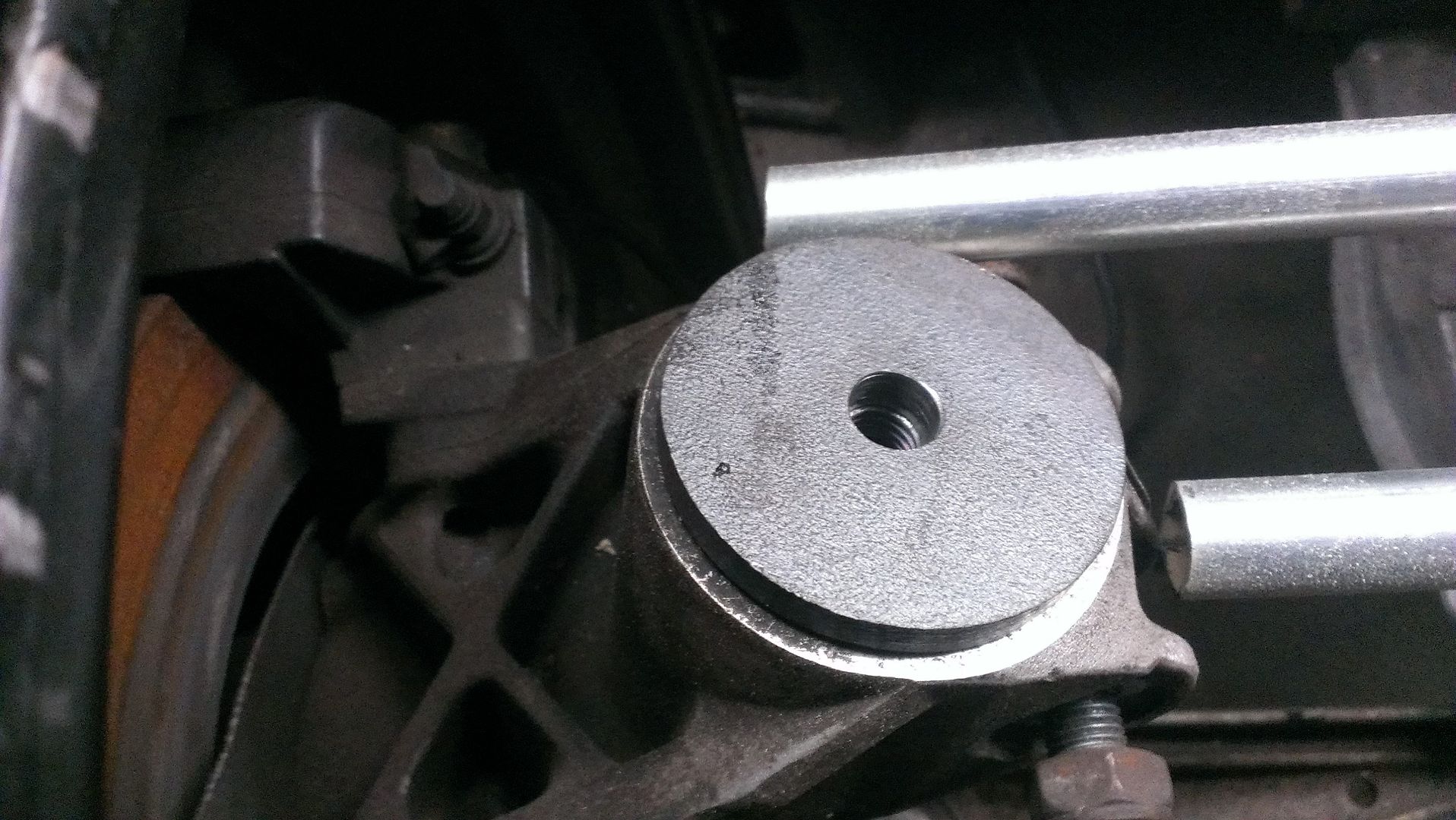
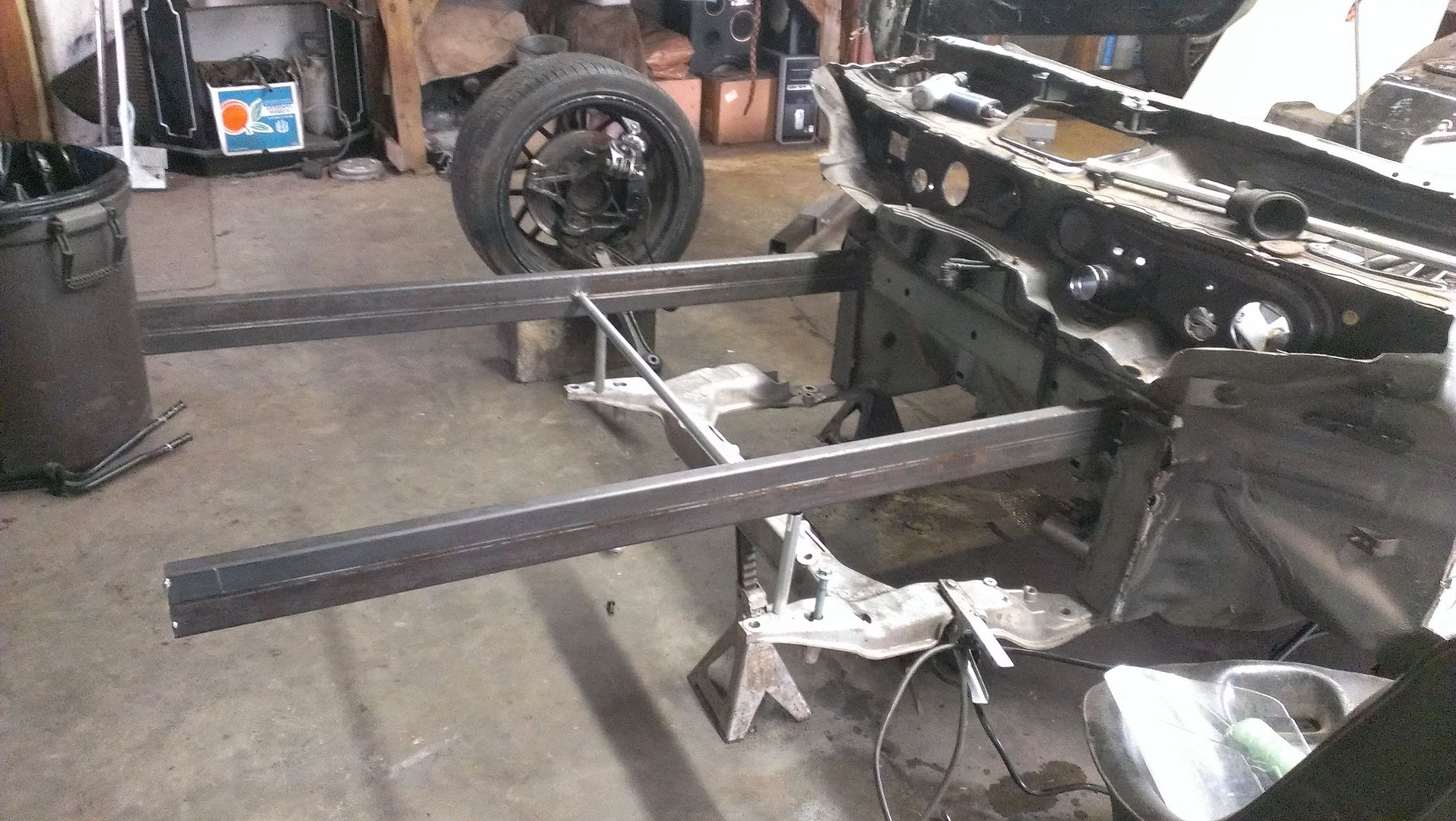
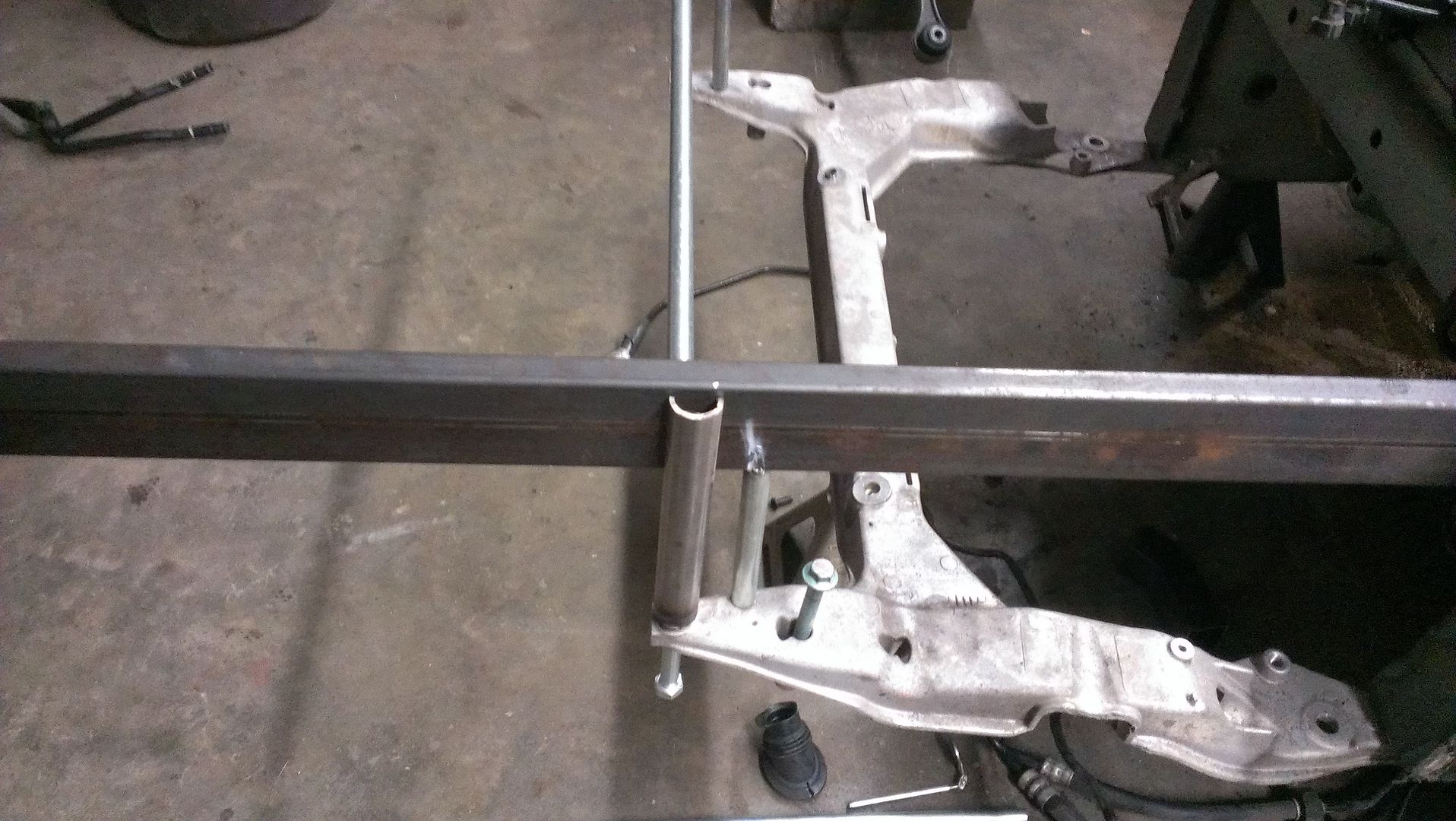
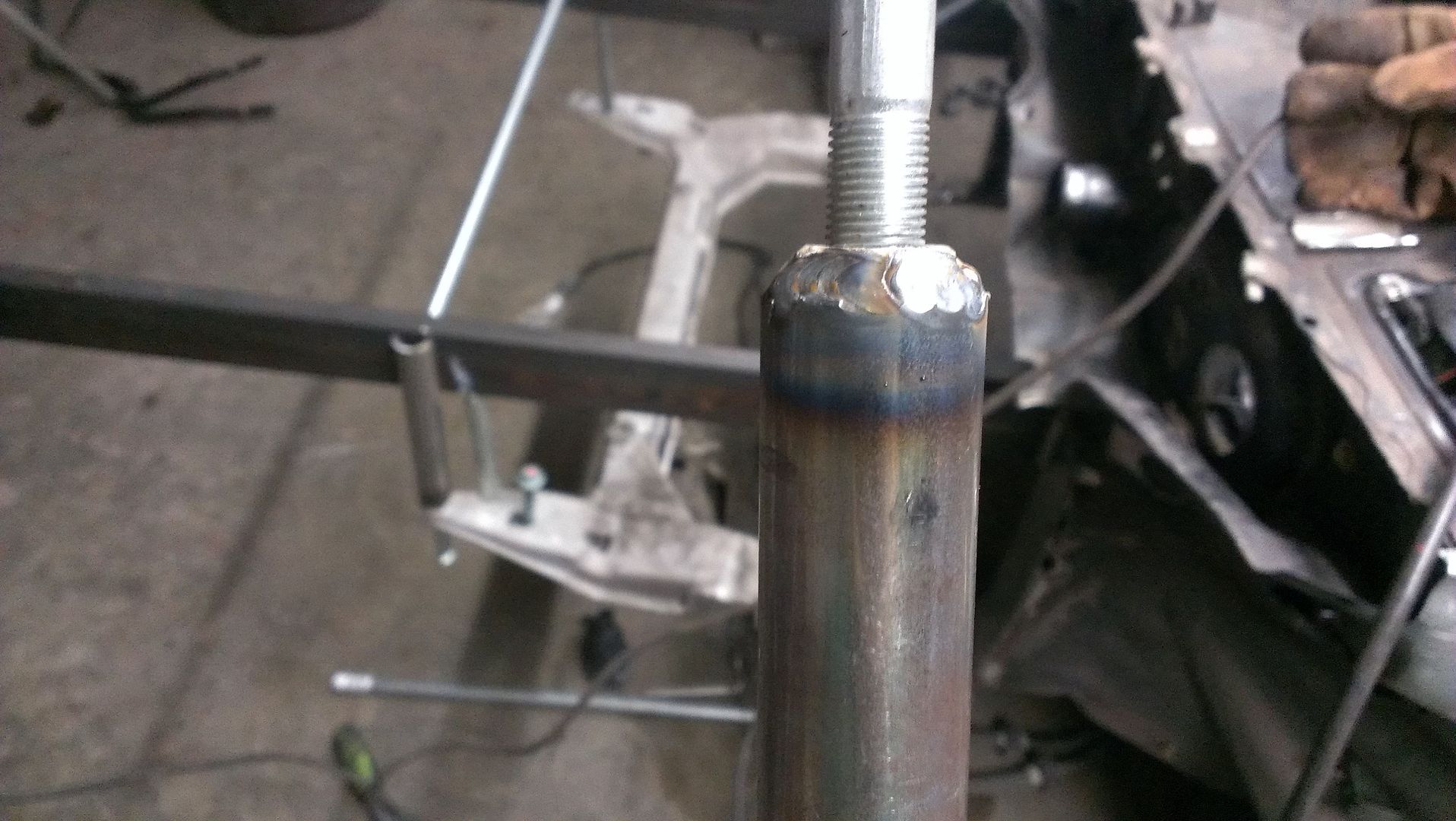
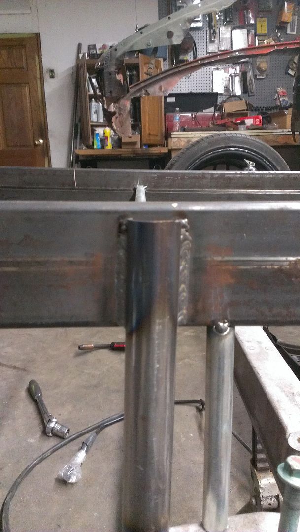
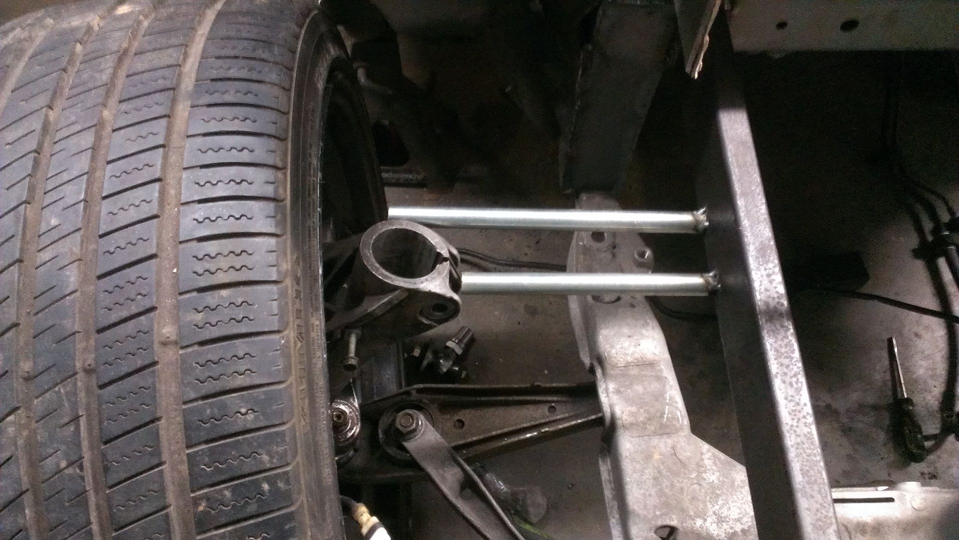
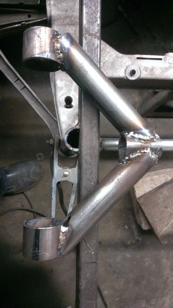
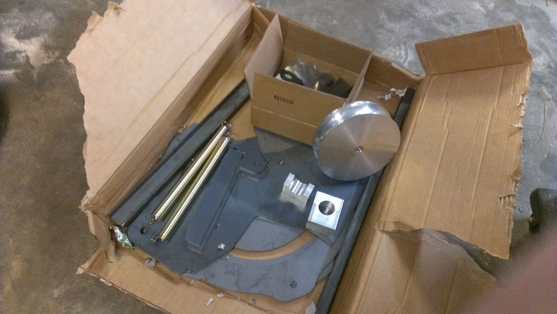
That said I have made a little progress.
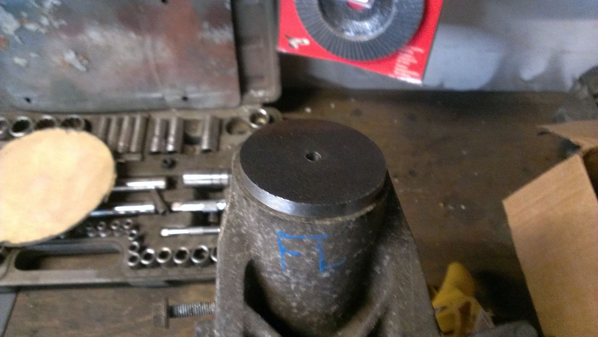
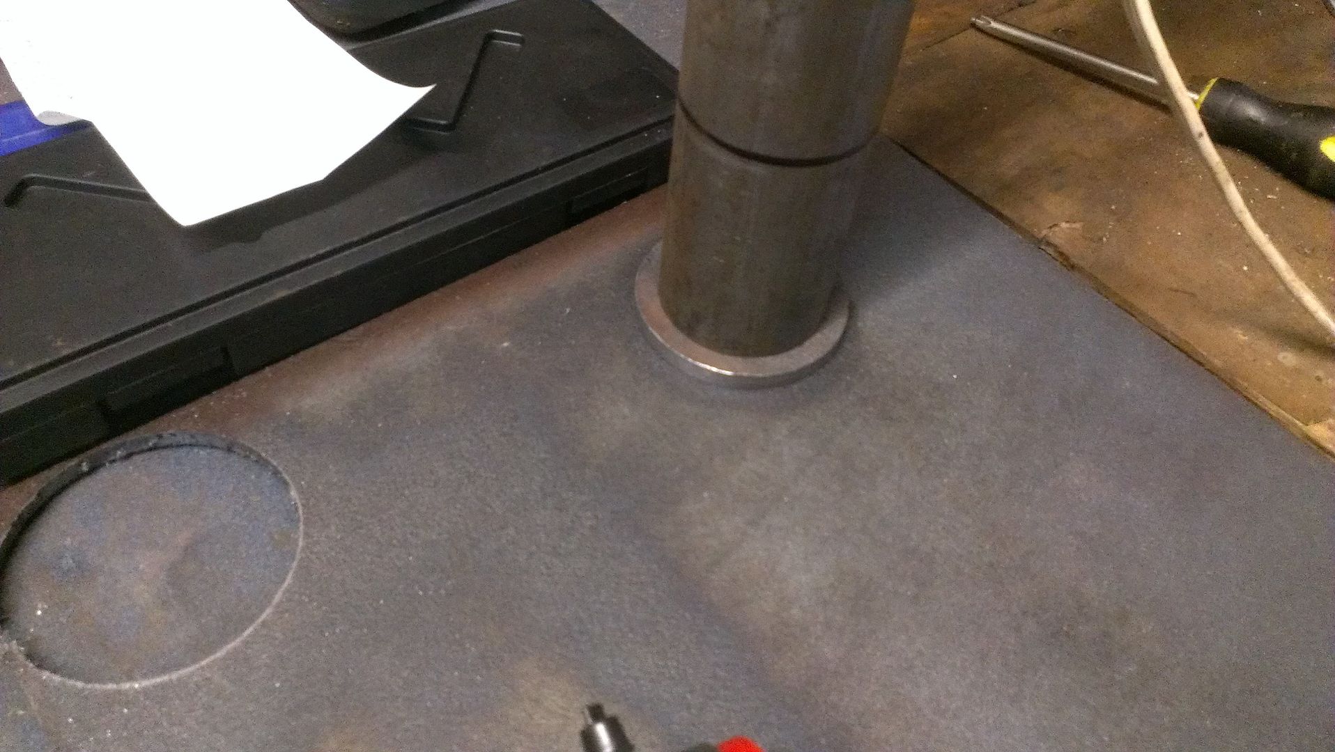
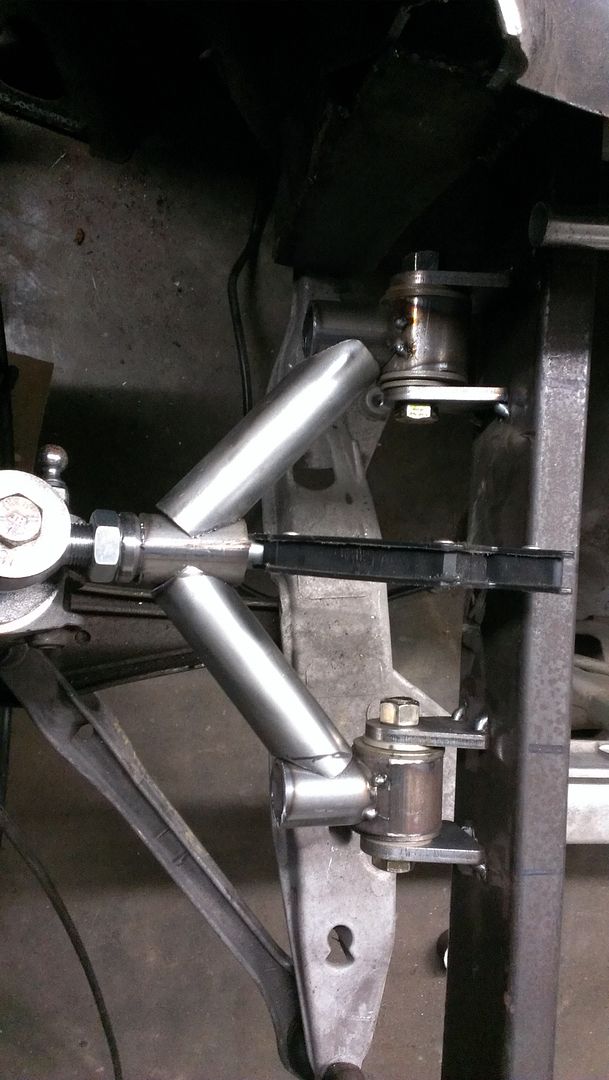
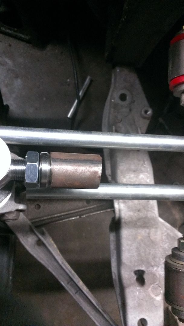
I made a proto type adapter today
|
|
|
|
|
04-08-2015, 10:17 PM
|
#13
|
|
Registered User
Join Date: Oct 2014
Location: Patriot IN
Posts: 41
|
|
|
|
|
|
04-08-2015, 10:42 PM
|
#14
|
|
Registered User
Join Date: Oct 2014
Location: Patriot IN
Posts: 41
|
|
|
|
|
|
04-08-2015, 10:44 PM
|
#15
|
|
Registered User
Join Date: Oct 2014
Location: Patriot IN
Posts: 41
|
|
|
|
|
|
04-08-2015, 10:53 PM
|
#16
|
|
Registered User
Join Date: Oct 2014
Location: Patriot IN
Posts: 41
|
|
|
|
|
|
04-10-2015, 07:55 AM
|
#18
|
|
Registered User
Join Date: Oct 2014
Location: Patriot IN
Posts: 41
|
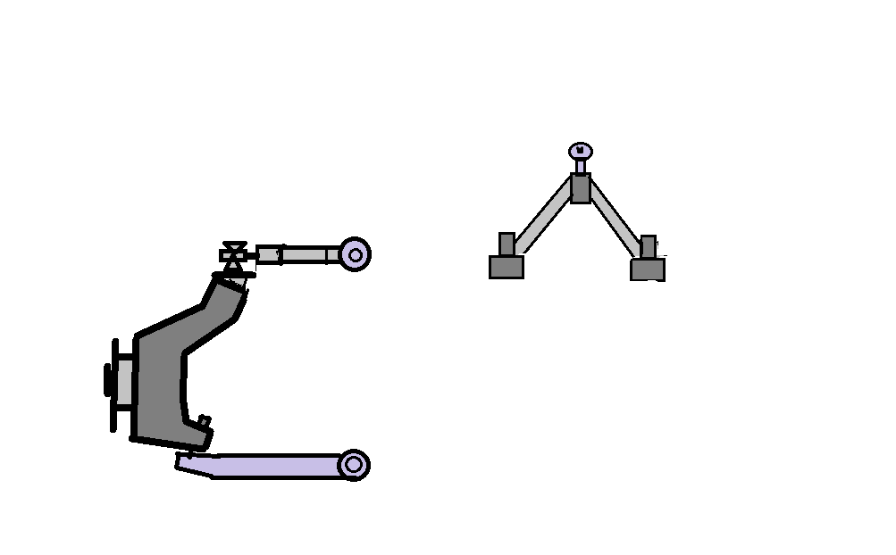
Yes I do, here is a quick ms paint rendering of my next prototype I plan on making. I plan to angle the him at the same degree as the hub adapter I will also be lowering the control arms mounts on the frame rails. To get the desired orientation of the control arms. All thoughts and Ideas are welcome.
|
|
|
|
|
04-18-2015, 10:16 PM
|
#19
|
|
Registered User
Join Date: Oct 2014
Location: Patriot IN
Posts: 41
|
I'm still playing with ideas I mocked up the angle the him idea it would fix the problem, however it would make it more difficult to go with second type of push rod suspension i'm thinking of doing in post 12.
here is another idea that would let me keep a straight control arm.
|
|
|
|
|
04-19-2015, 12:52 AM
|
#20
|
|
Registered User
Join Date: Jul 2008
Location: San Jose, CA
Posts: 207
|
Someone please make Exocet style kit for Boxsters. LOL.
|
|
|
|
 Posting Rules
|
You may not post new threads
You may not post replies
You may not post attachments
You may not edit your posts
HTML code is On
|
|
|
All times are GMT -8. The time now is 06:43 PM.
| |


 Linear Mode


