Go Back   986 Forum - The Community for Porsche Boxster & Cayman Owners > Porsche Boxster & Cayman Forums > Boxster General Discussions

Post Reply
 
LinkBack Thread Tools Display Modes
Old 10-03-2017, 10:03 AM   #1
Registered User
 
bcinphx's Avatar
 
Join Date: Aug 2016
Location: Arizona
Posts: 75
Where does this go - vacuum valve

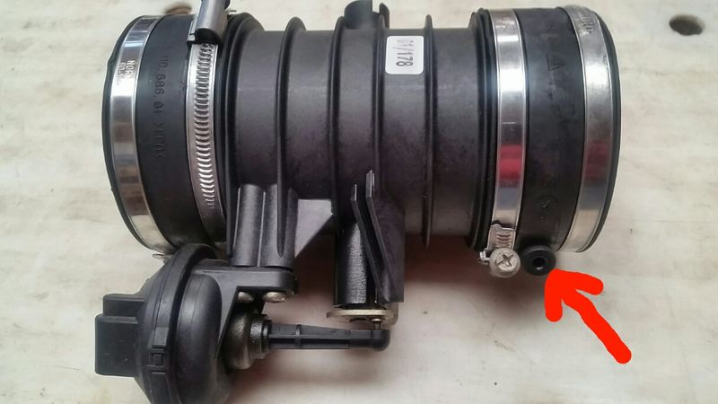
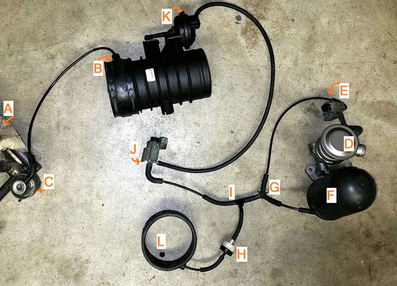
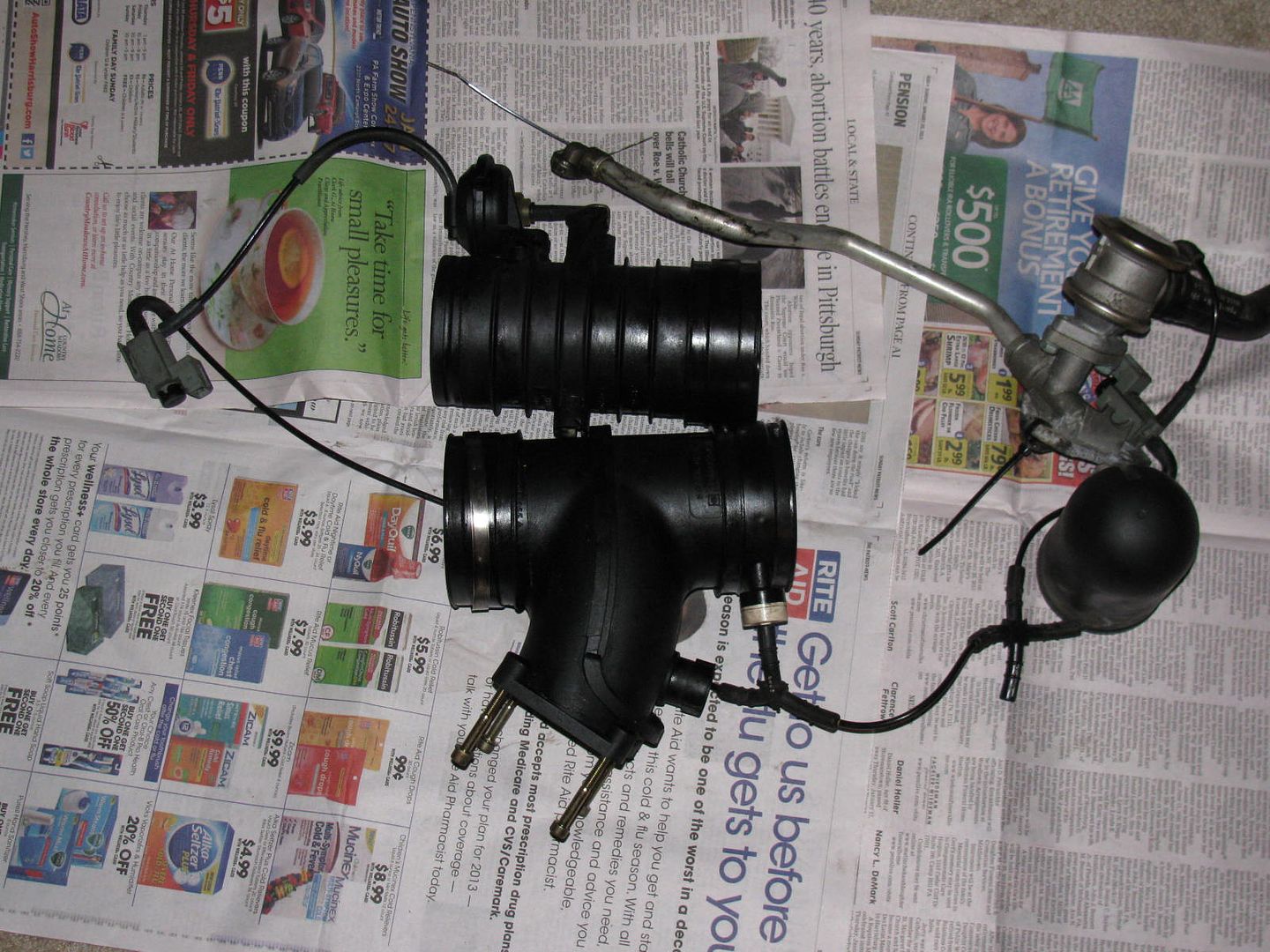
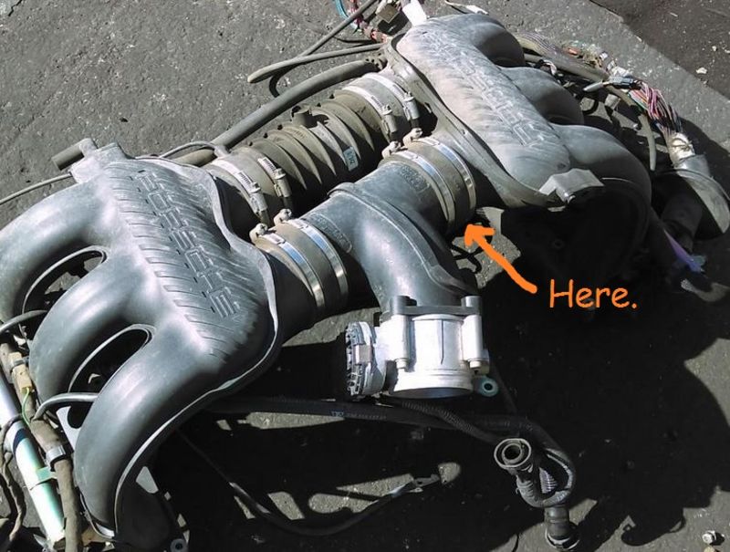
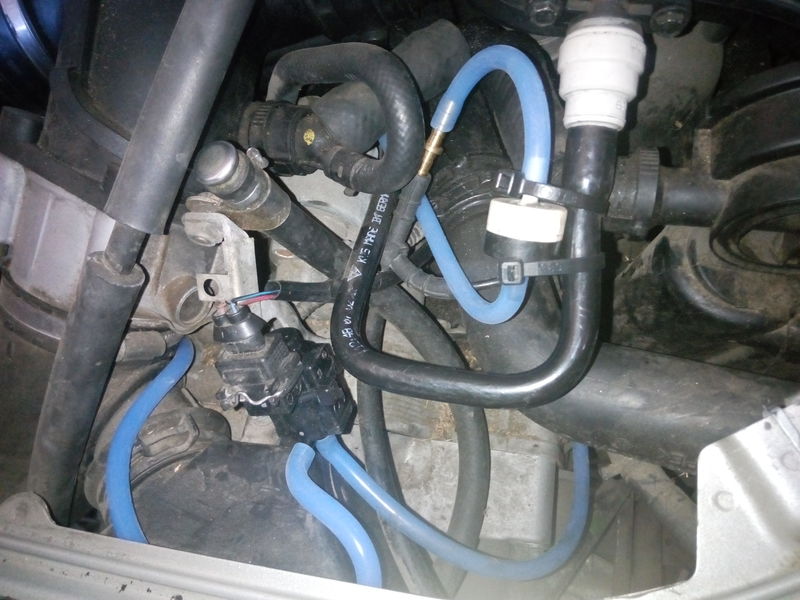
I have read the post by Rochan below....I know this has been beat to death, but particlewave suggested I start a general discussion. Two pictures are included. I broke the line going to the Green Arrow - I know where it goes. My question is where does the end piece of the valve go marked with the yellow arrow. The other picture is from the intake boot with where I think the valve fell out of, marked by the Red Arrow (same pic as 78F350 published) but, this little tube does not go through on my intake tube - it is blocked and has never been open. The vacuum valve at the yellow arrow cannot work if it has a blocked orifice. Need some help! 2002 S
Thanks, Bill


__________________
Bill
02 Boxster S
01 Carrera Cab
91 BMW 850i
71 MGB GT

Last edited by bcinphx; 10-03-2017 at 12:54 PM. Reason: Clarification
bcinphx is offline   Reply With Quote
Old 10-03-2017, 11:13 AM   #2
Motorist & Coffee Drinker
 
78F350's Avatar
 
Join Date: Jul 2014
Location: Oklahoma
Posts: 3,672
Garage
Bill, take a look at these two posts and see if you can sort it out:
Quote:
Originally Posted by 78F350 View Post
In regard to the vacuum connections, here's that diagram, created with actual parts from a scrapped 2001 2.7L.

Notes:
-This picture shows what connections have to be made, the actual order of connections to the Y fittings (I) and (G) are not critical.
-The Tiptronic cars will have a 4-way connection at (I) or (G) with a line running to a changeover valve on the transmission.

It looks like a mess of tubes and parts, but in function it is fairly simple.
This shows 3 vacuum powered components: SAI, Resonance Flapper, and Fuel Pressure Regulator. Brake booster vacuum system is not shown.
SAI: Vacuum source -> electric change-over valve (E) -> change-over valve (D).
Resonance Flapper: Vacuum source -> electric change-over valve (J) -> vacuum unit (K).
Fuel Pressure Regulator: Vacuum source (B) -> Pressure regulator (C) -> injector valves (A).

Rubber sleeves (L) and (B) are the source of vacuum from the intake. (H) is a check valve. (F) is the vacuum reservoir.
Note that (L) in the above diagram is placed on the junction to the right of the throttle body.

Quote:
Originally Posted by jsceash View Post
On a 2003, Driver side intake manifold has a vacuum switch between cylinder 4 and 5 intake risers. A line comes off the bottom of that switch and goes to the Y connector near the vacuum tank the other end goes to a connection on the underside of the passenger side plenum collar. The same switch has a second tube that goes to the diaphragm you pictured. I have an engine apart now and can probably get you a couple pictures

Hope that solves it for you.
__________________
I am not an attorney, mechanic, or member of the clergy. Following any advice given in my posts is done at your own peril.
78F350 is offline   Reply With Quote
Old 10-03-2017, 11:28 AM   #3
Motorist & Coffee Drinker
 
78F350's Avatar
 
Join Date: Jul 2014
Location: Oklahoma
Posts: 3,672
Garage
Additionally, note that on the 2002 and later models, such as yours, the connection marked in red is not used. On the older cars that is the vacuum source for the fuel pressure regulator.


Only the connection on the tube closer to the throttle body is used on yours.


That do it?
__________________
I am not an attorney, mechanic, or member of the clergy. Following any advice given in my posts is done at your own peril.
78F350 is offline   Reply With Quote
Old 10-03-2017, 12:45 PM   #4
Registered User
 
bcinphx's Avatar
 
Join Date: Aug 2016
Location: Arizona
Posts: 75
Thx Jon. Going to check now. I love pictures.
Bill
__________________
Bill
02 Boxster S
01 Carrera Cab
91 BMW 850i
71 MGB GT
bcinphx is offline   Reply With Quote
Old 10-03-2017, 05:43 PM   #5
Registered User
 
Join Date: Sep 2017
Location: MALIBU
Posts: 166
Here is my setup. Brass barbed fitting into the manifold is hidden behind the hose

__________________
2003Boxster
1973 Carreras RS tribute
2000 Saab Aero wagon stick
1990 Chevrolet pu pre runner
boxfix is offline   Reply With Quote
Old 10-04-2017, 06:33 AM   #6
Registered User
 
bcinphx's Avatar
 
Join Date: Aug 2016
Location: Arizona
Posts: 75
Thanks for the pictures and the diagrams and the advice guys. Mine doesn't look like any of these. I do not have an orifice on the collar. Now I can't even find the line which broke going to the Tiptronic transmission. I'll have to put it on the lift to see if I can find where it comes out of the transmission. If anybody knows where this comes out of the transmission please let me know. I will probably now have to pull the alternator so that I can see more. I have looked at so many diagrams I'm going stir-crazy. I do have about 10 feet of new plastic tube. Thanks guys
__________________
Bill
02 Boxster S
01 Carrera Cab
91 BMW 850i
71 MGB GT
bcinphx is offline   Reply With Quote
Old 10-05-2017, 01:45 PM   #7
Registered User
 
bcinphx's Avatar
 
Join Date: Aug 2016
Location: Arizona
Posts: 75
Found all the hoses at replaced them all. Found the worst one underneath the vacuum canister hard to get to but got it all done thanks guys for everything.

__________________
Bill
02 Boxster S
01 Carrera Cab
91 BMW 850i
71 MGB GT
bcinphx is offline   Reply With Quote
Post Reply


Posting Rules
You may not post new threads
You may not post replies
You may not post attachments
You may not edit your posts

BB code is On
Smilies are On
[IMG] code is On
HTML code is On
Trackbacks are On
Pingbacks are On
Refbacks are On


All times are GMT -8. The time now is 02:34 AM.


Powered by vBulletin® Version 3.8.7
Copyright ©2000 - 2024, vBulletin Solutions, Inc.
Content Relevant URLs by vBSEO 3.6.0
Copyright 2024 Pelican Parts, LLC - Posts may be archived for display on the Pelican Parts Website -    DMCA Registered Agent Contact Page